Component Mechanical Seal
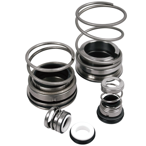
Consist of two basic parts called faces. One face rotates with the shaft, while a second is held stationary in the pump housing. The primary seal is created between these two seal faces. Click here to view the Pump Report on this topic.
What is a component mechanical seal?
Component mechanical seals consist of two basic parts called faces. One face rotates with the shaft, while a second is held stationary in the pump housing. The primary seal is created between these two seal faces.
How does a component mechanical seal work?
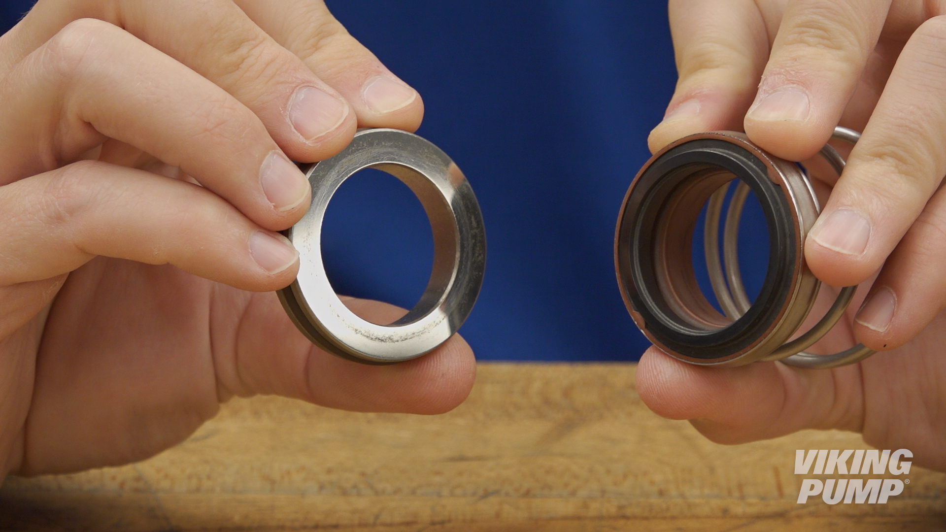
Component mechanical seals work by utilizing two separate seal faces. One seal face (static) is typically installed into the pump housing, or bracket, while the other (rotary face) is installed onto the pump shaft. These two seal faces are glossy and highly finished. When liquid is being pumped, process fluid will work it’s way toward the seal faces. When liquid finally enters the space between the seal faces, a hydrodynamic film is created which creates the seal and lubricates the faces. This is the primary seal. A spring helps hold the seal faces together to maintain the primary seal.
Secondary seals are created by o-rings, bellows, or gaskets that prevent leakage past the gland or along the shaft.
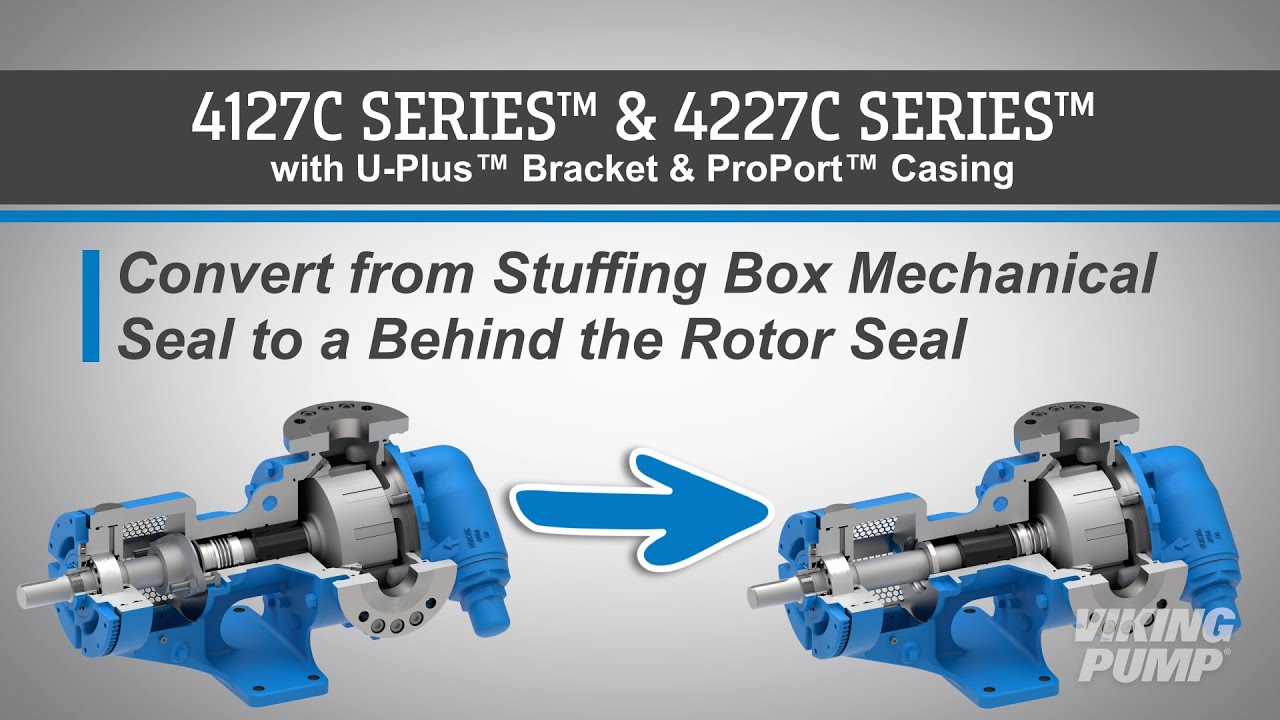
How to install a mechanical Seal
Here are some basic steps for installing a cartridge seal. These steps will vary depending on the type of seal and the pump technology it’s going into, but for this example these steps relate to installing a cartridge mechanical seal into Viking Pump’s 4124A Series™.
| 1. Place the seal installation sleeve into the shaft and lubricate the sleeve and shaft. | 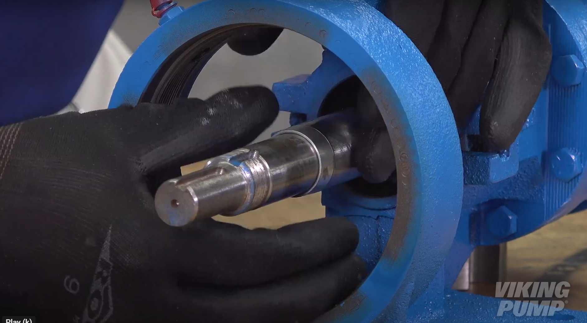 |
| 2. Slide the seal assembly onto the shaft and over the installation sleeve until the assembly contacts the bracket face. | 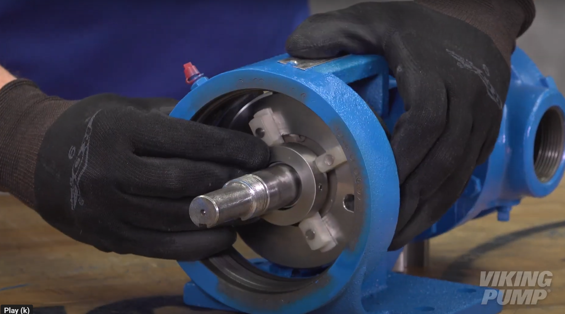 |
| 3. Remove the installation sleeve. | |
| 4. Reassemble the pump and set the end clearance. | |
| 5. Install the gland cap screws. Do not fully tighten at this time. | 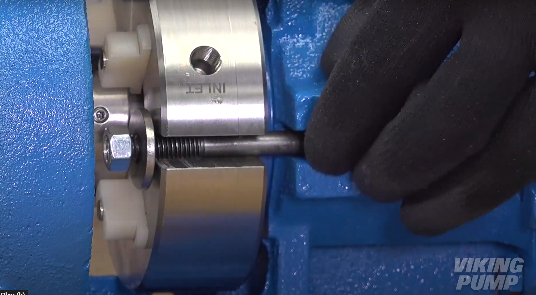 |
| 6. Turn the shaft several times to center the seal. | |
| 7. Tighten the cap screws tight enough to compress the seal gasket. | |
| 8. Evenly tighten the seal sleeve set screws to set the collar to the shaft. | 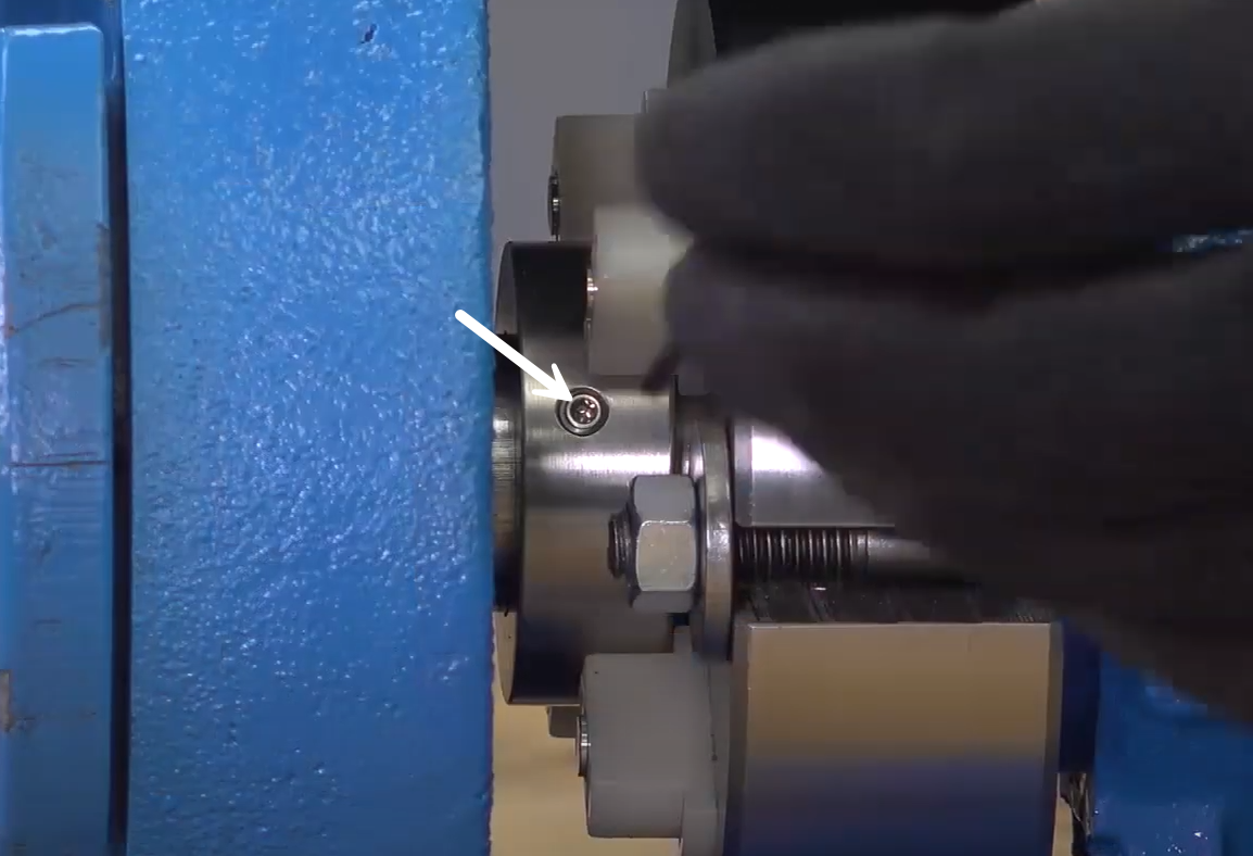 |
| 9. Rotate or remove the seal spacers and check rotation. | 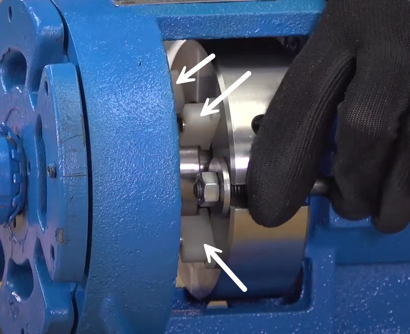 |
| 10. Reconnect seal plan or plug unused connections. | |


March 25, 2025

February 21, 2025
December 04, 2024