Lip Seal
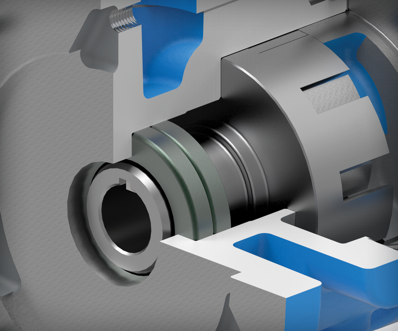
Consists of a flexible elastomeric lip in a rigid housing. The lip seal is stationary and the shaft rotates inside. Click here to view the Pump Report on this topic.
What is a lip seal?
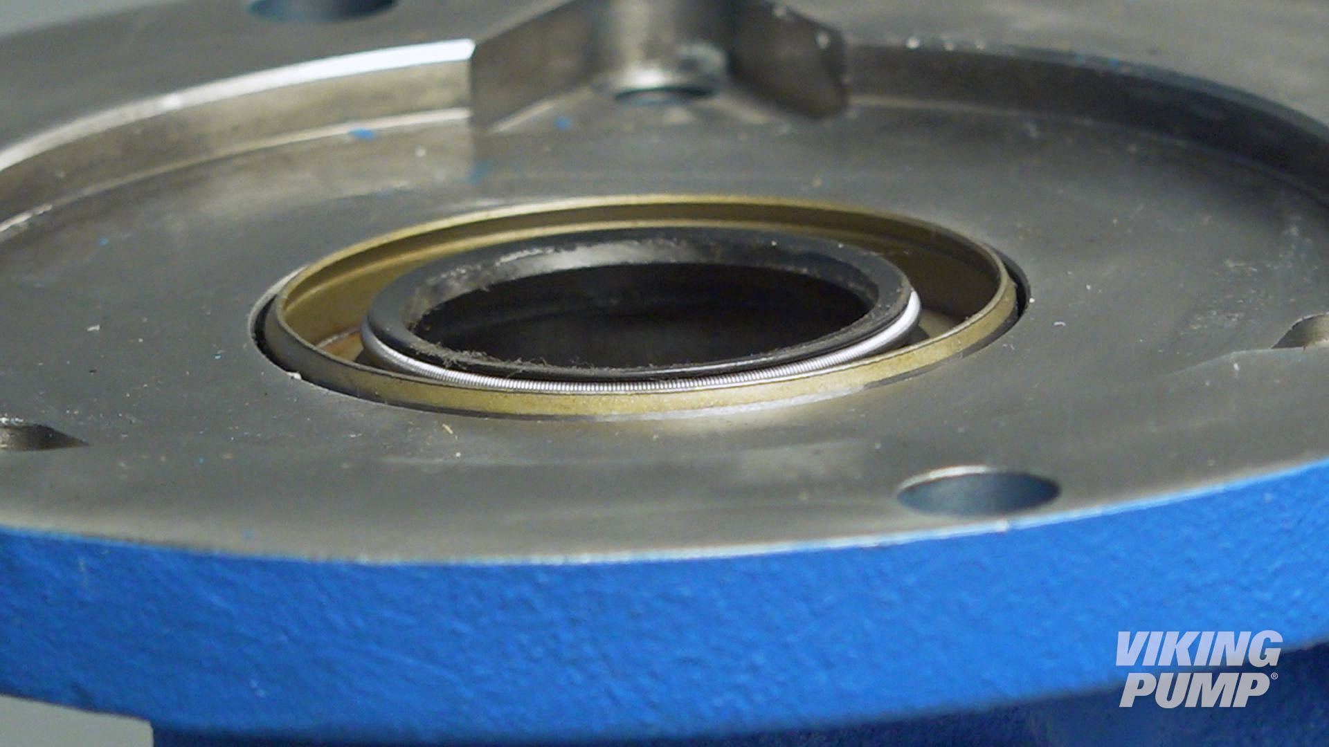
Lip seals consist of a flexible elastomeric lip inside a rigid housing.
The lip seal is stationary and the shaft rotates inside.
An inboard spring helps to energize the lip and keep it in contact with the shaft while an outboard lip, called a wiper, prevents the ingress of contaminants from the outside environment.
Click here to view the Pump Report on this topic.
What are the benefits of using a lip seal in a pump?
Lip seals are a simple, economical, and compact seal solution. Their narrow profile makes them easy to fit into small pumps and tight spaces.
What are the limitations of lip seals?
Lip seals are not ideal for abrasive applications and they have modest inlet pressure limits when compared to other seal technologies.
How to install a lip seal
Here are some basic steps for installing a lip seal. These steps will vary depending on the type of seal and the pump technology it’s going into, but for this example these steps relate to installing a lip seal into Viking Pump’s G and GG sized 75 Series™ pumps.
Note: Before any work begins on a pump, please consult the appropriate technical service manual for safety information. A copy of the latest revision can be found on our website.
What you need for installation
To install the two lip seals into a G or GG sized 75 Series™ pump, you’ll need two pieces of equipment:
- Arbor Press
- 2 ¾” press fixture
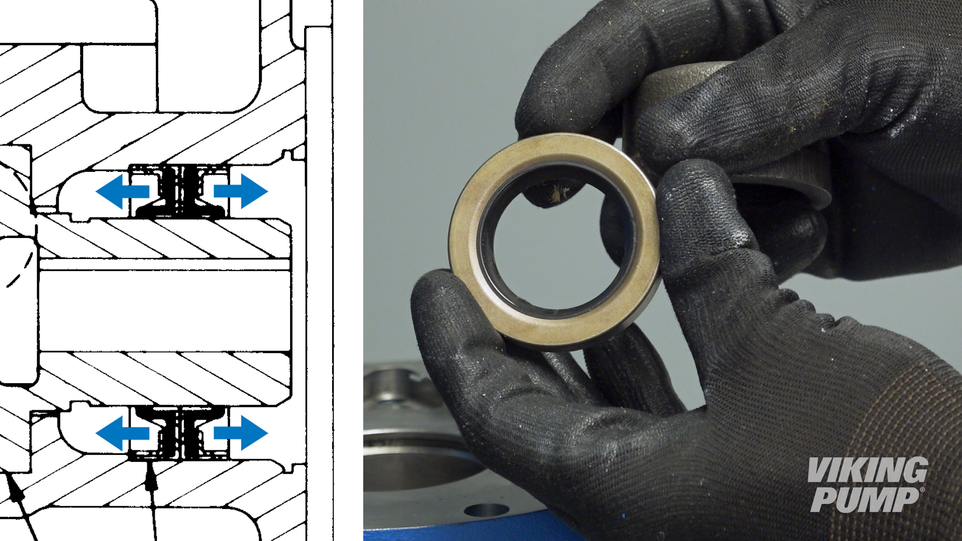
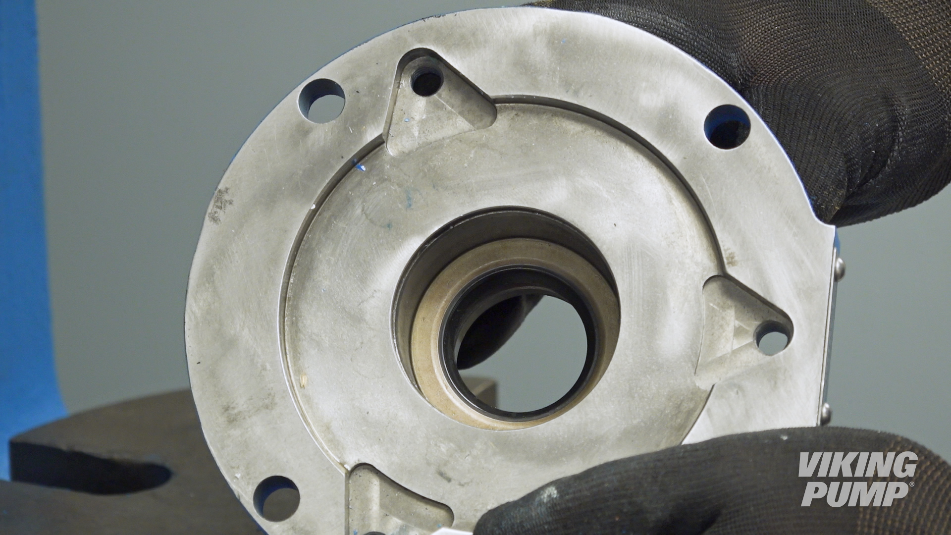
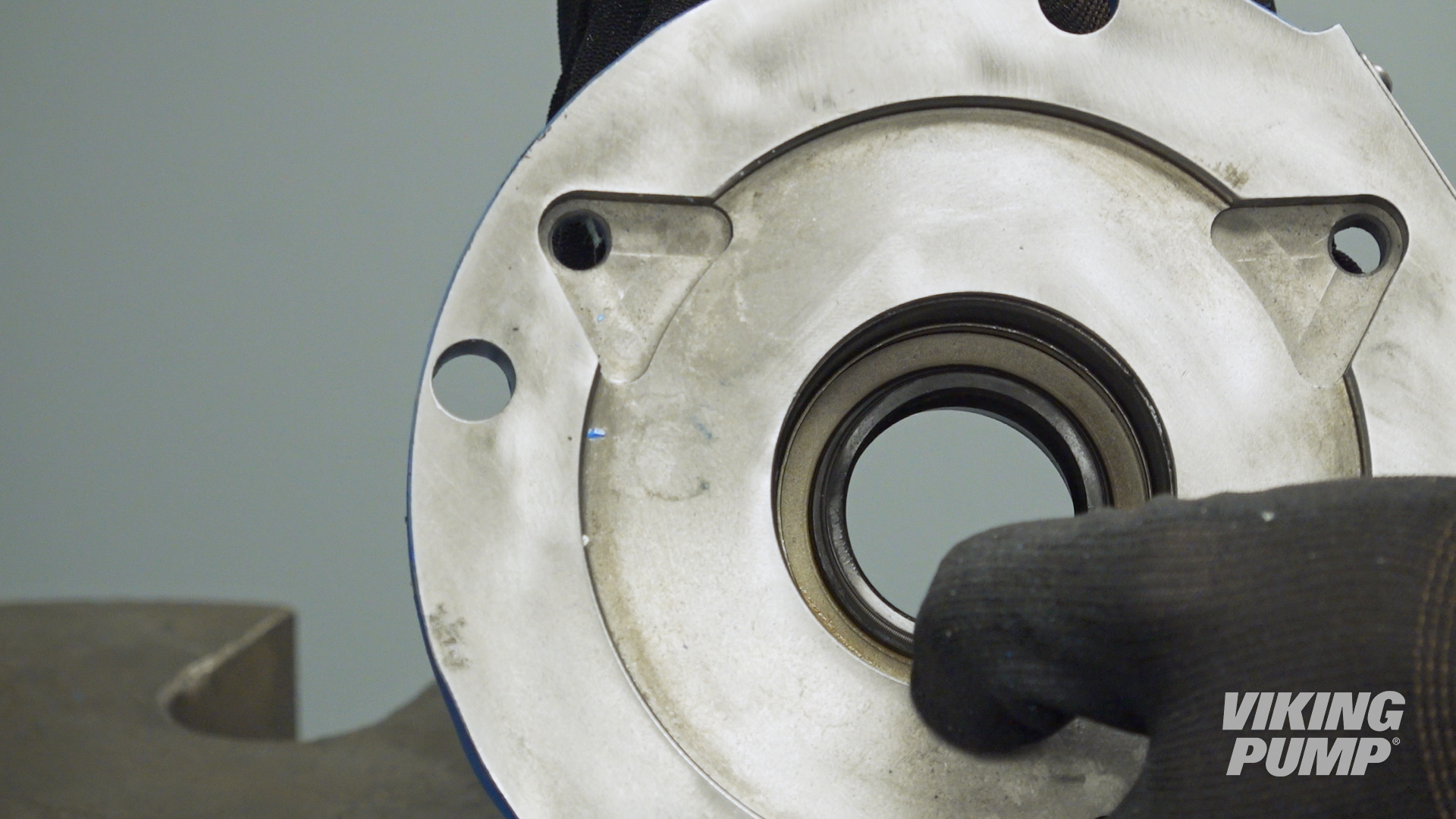
Pressing in the sealsThe 75 Series™ has two lip seals that are pressed in one at a time. The lips face outward from each other when installed. For G and GG sized pumps, the lip seals will be pressed in from the flange side of the pump. |
 |
| Place the first lip seal into the bore with the lip down. | 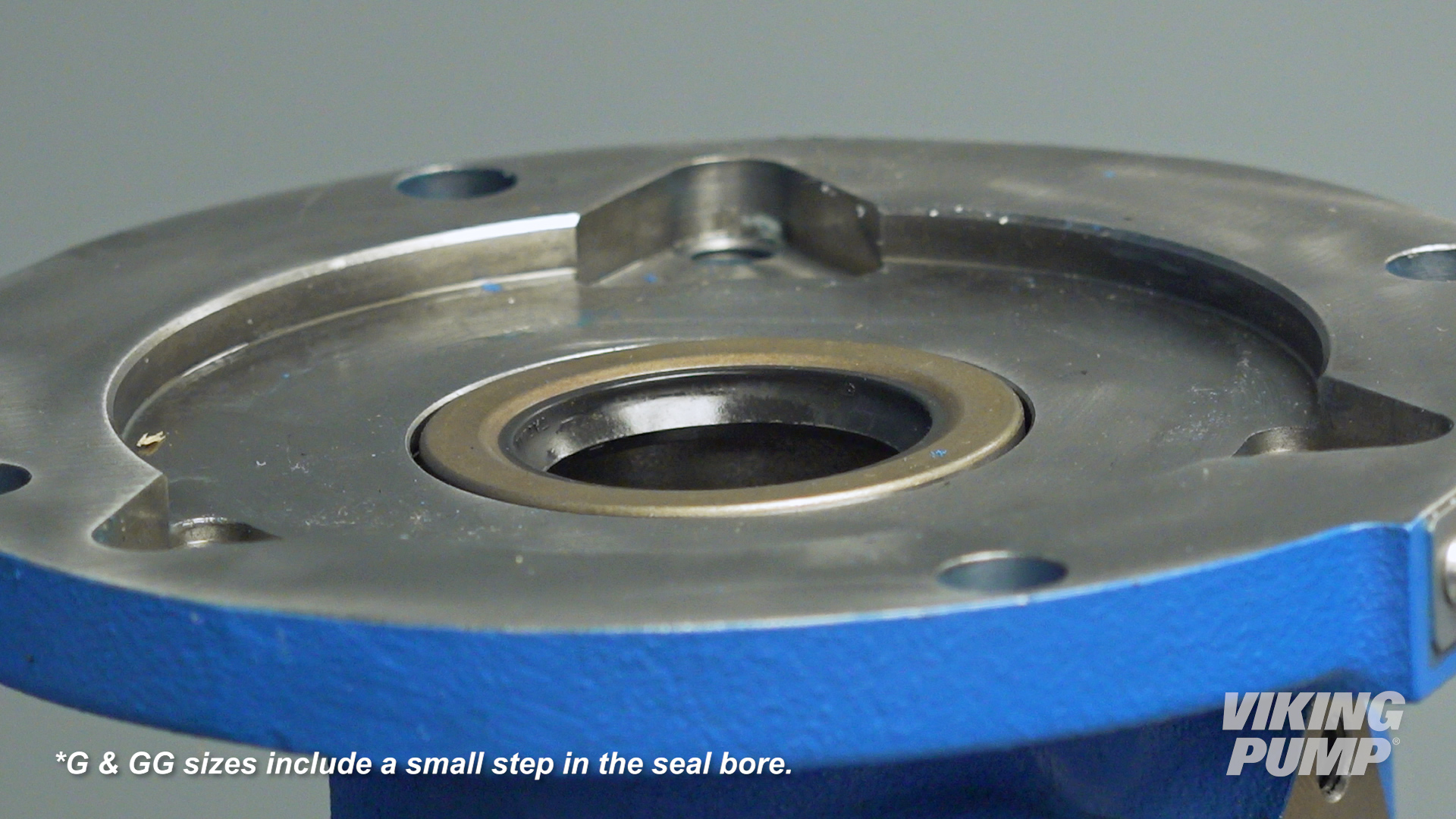 |
| Press until it stops at the bottom of the seal bore. |
|
| Place the second lip seal with the lip facing up and press until it stops against the first lip seal. |
|
| Pack the area between the lips with compatible grease. |  |
| You can now complete the rest of the pump assembly. | |


March 25, 2025

February 21, 2025
December 04, 2024