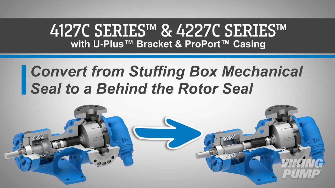
Behind the Rotor Seal
Any pump wherein the seal is located directly behind the rotor, isolating the shaft bushings or bearings from the pumped liquid. An alternative to pumps with seals located in the stuffing box.
What is a behind the rotor seal?
A behind the rotor seal is a type of mechanical seal that is located directly behind the rotor, isolating the shaft bushings or bearings from the pumped liquid. This type of seal is an alternative to seals that are located in the stuffing box of the pump.
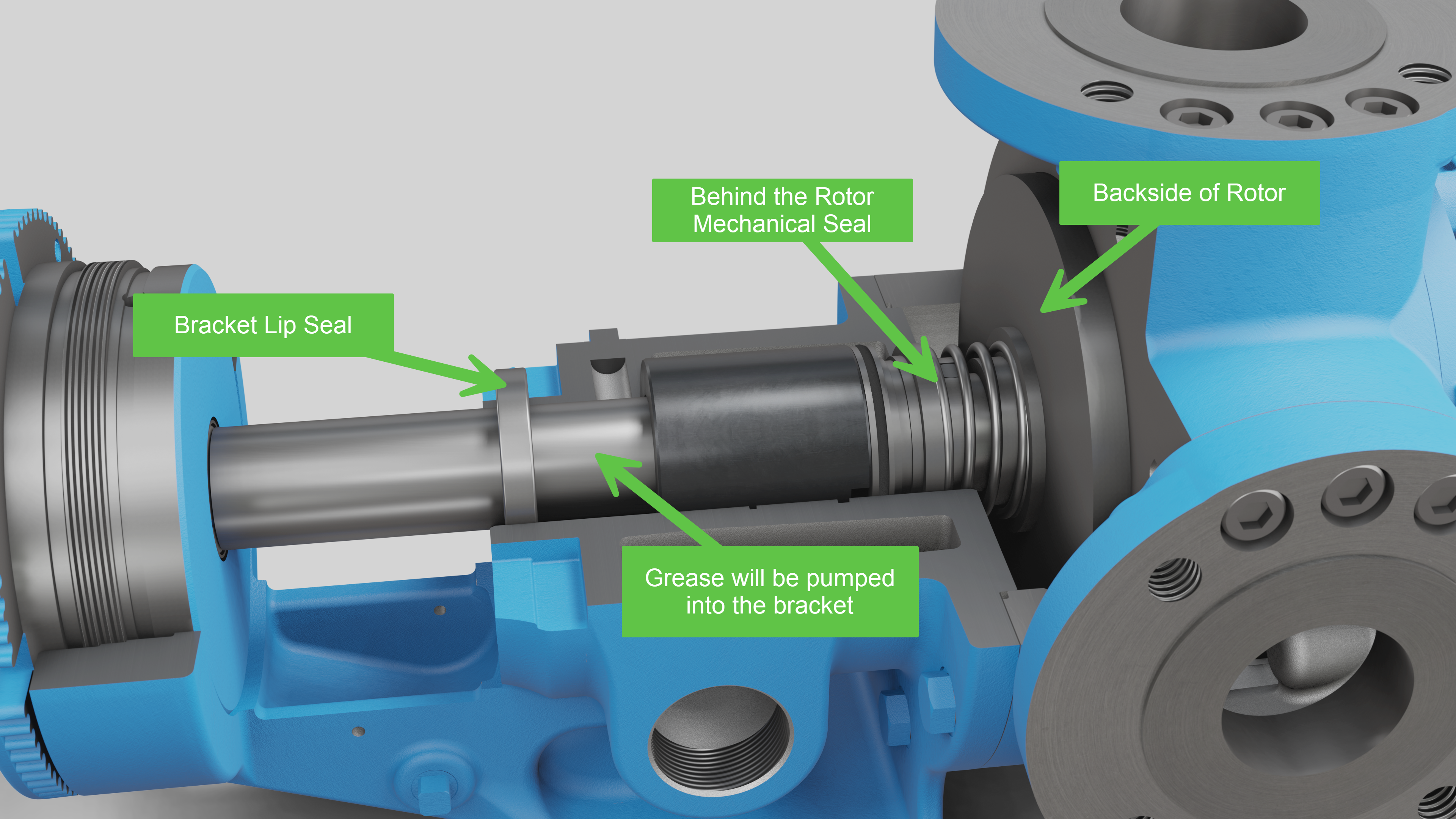
Because the rotating shaft is not being lubricated by the process liquid, the bracket must be filled with an application appropriate grease. A lip seal is installed in the face of the bracket to maintain the grease barrier.
How does a behind the rotor seal work?
Behind the rotor mechanical seals work by utilizing two separate seal faces. One seal face (static) is typically installed into the pump housing, or bracket, while the other (rotary face) is installed onto the base of the pump shaft against the rotor. These two seal faces are glossy and highly finished. When liquid is being pumped, process fluid will work it’s way toward the seal faces. When liquid finally enters the space between the seal faces, a hydrodynamic film is created which creates the seal and lubricates the faces. This is the primary seal. A spring helps hold the seal faces together to maintain the primary seal.
Secondary seals are created by o-rings, bellows, or gaskets that prevent leakage past the gland or along the shaft.
How do you install a behind the rotor seal?
Here are some basic steps for installing a behind the rotor seal. These steps will vary depending on the type of seal and the pump technology it’s going into, but for this example these steps relate to installing a single component PTFE behind the rotor seal into a stainless steel internal gear pump.
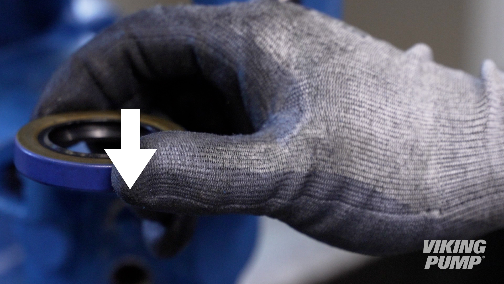
| 1. With the pump disassembled, first install the bracket lip seal by using an arbor or hydraulic press. Install with the spring side down until it is flush with the face of the bracket. |
|
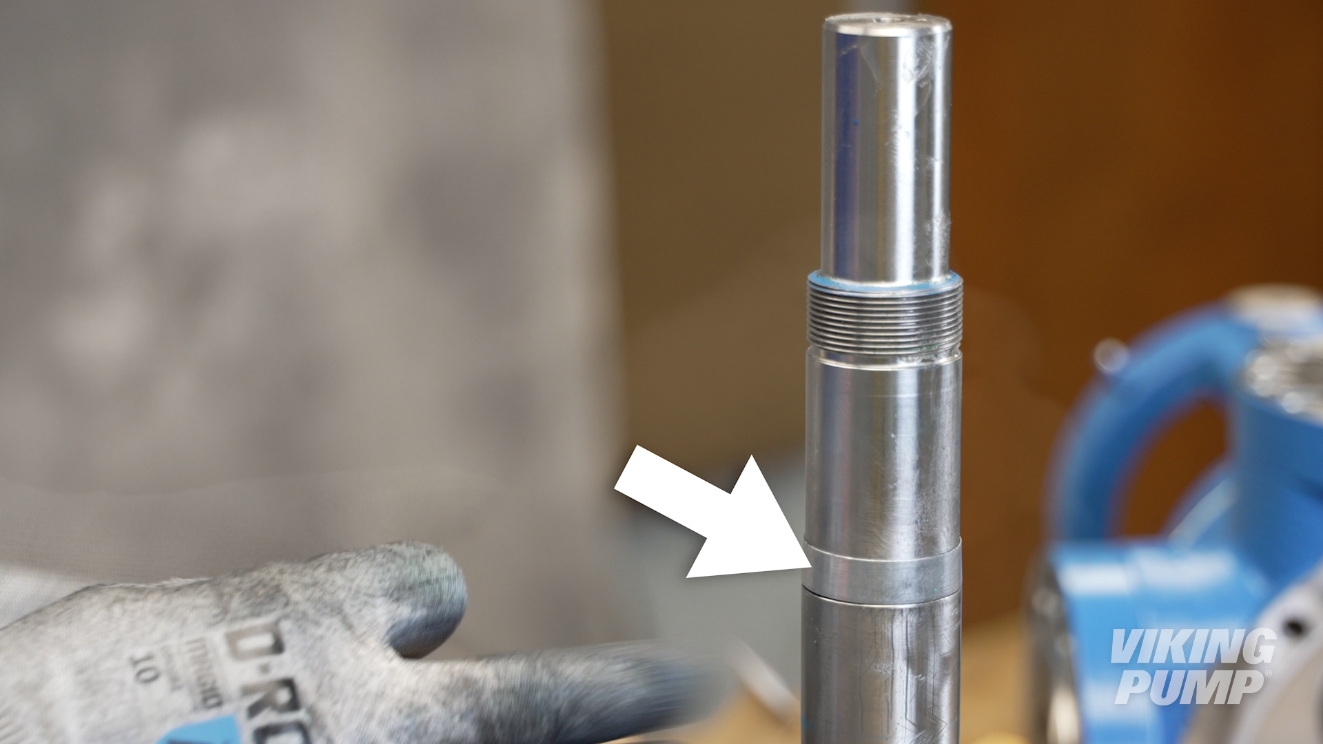
| 2. Install the provided installation sleeve onto the shaft. Make sure to lubricate the sleeve and shaft. Then install the seal rotary member until it makes contact with the back of the rotor. Then tighten the seal set screws evenly. |
|
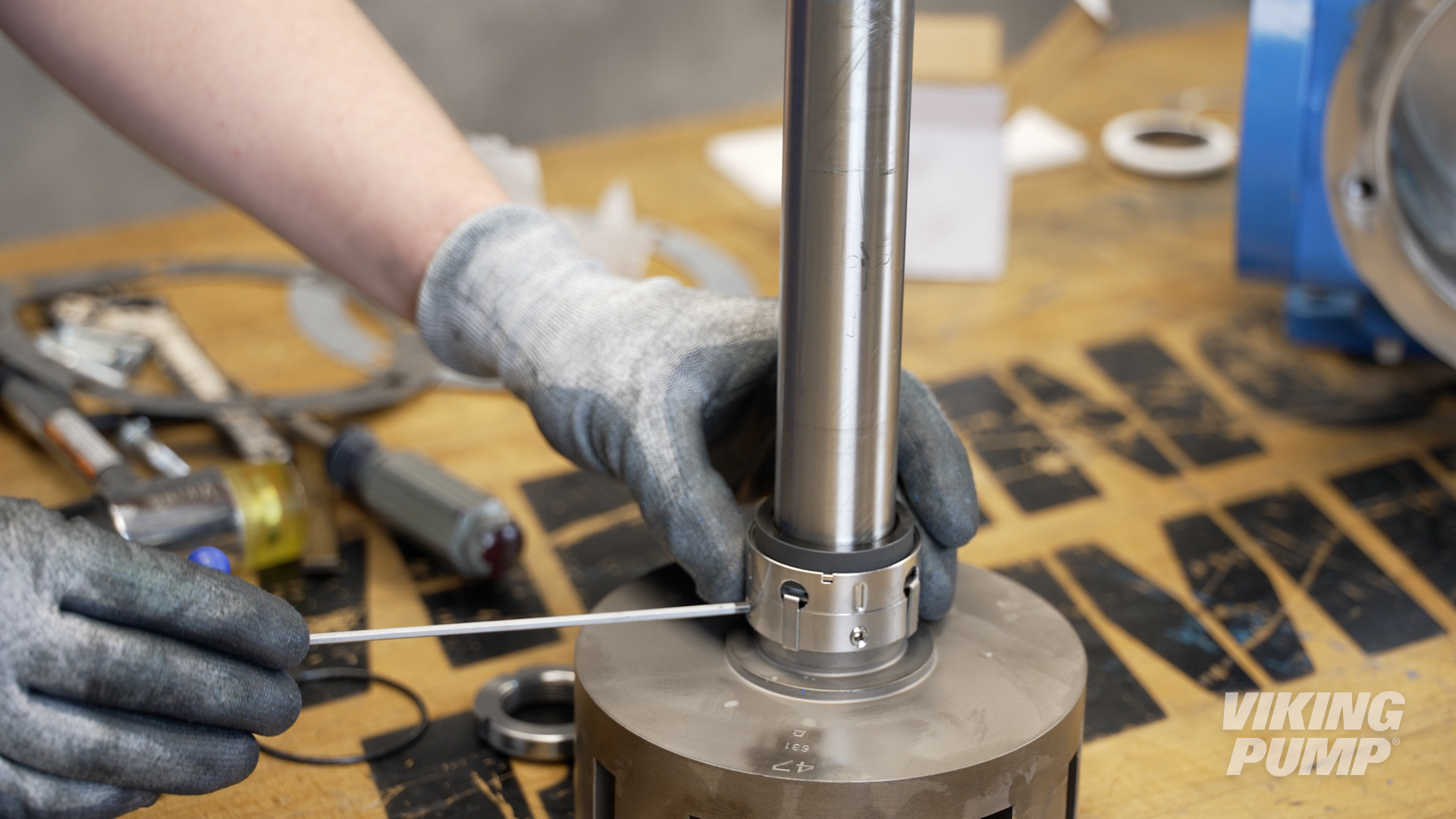
| 3. Remove the seal clips to engage the seal. | 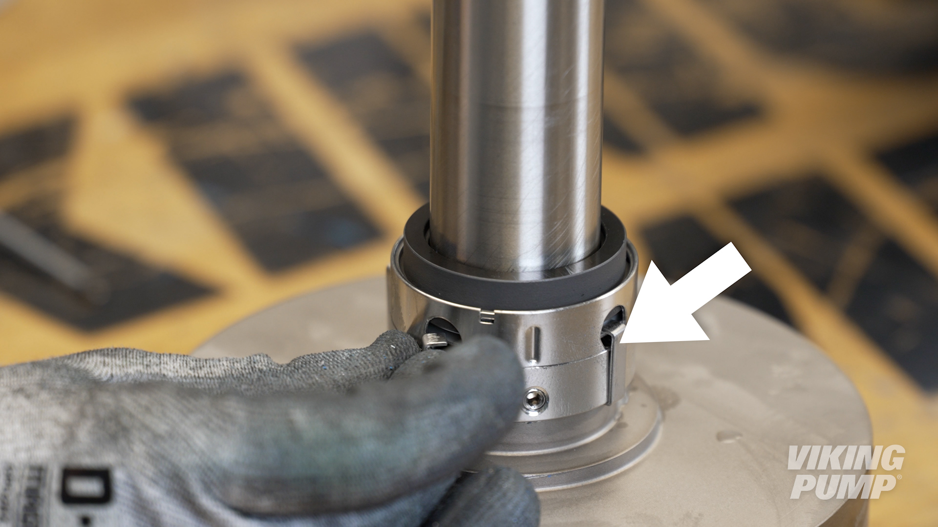 |
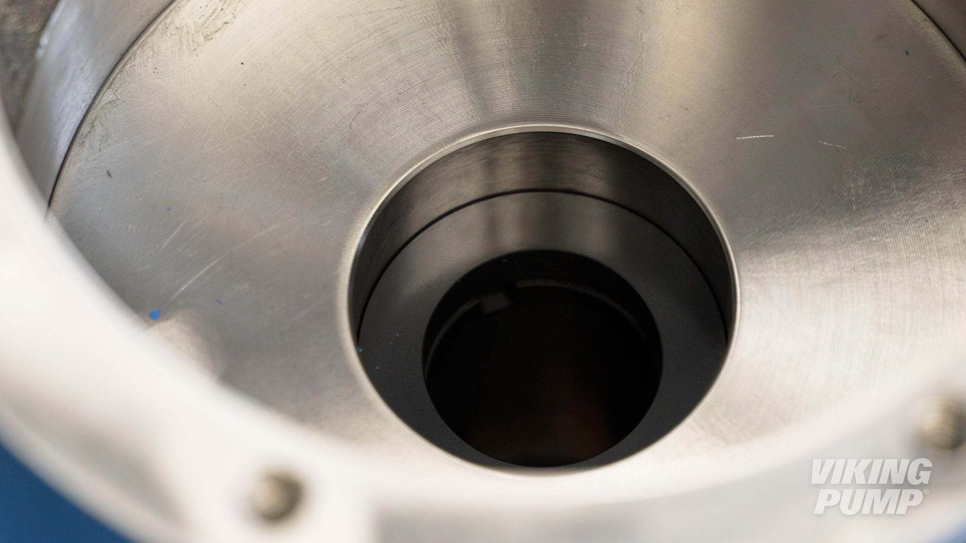
| 4. Next, with the pump oriented vertically with the bracket down, install the seal spacer ring. | 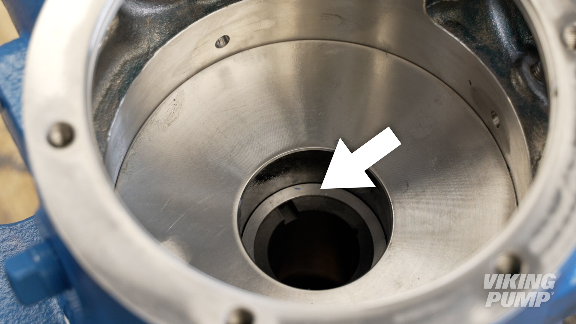 |
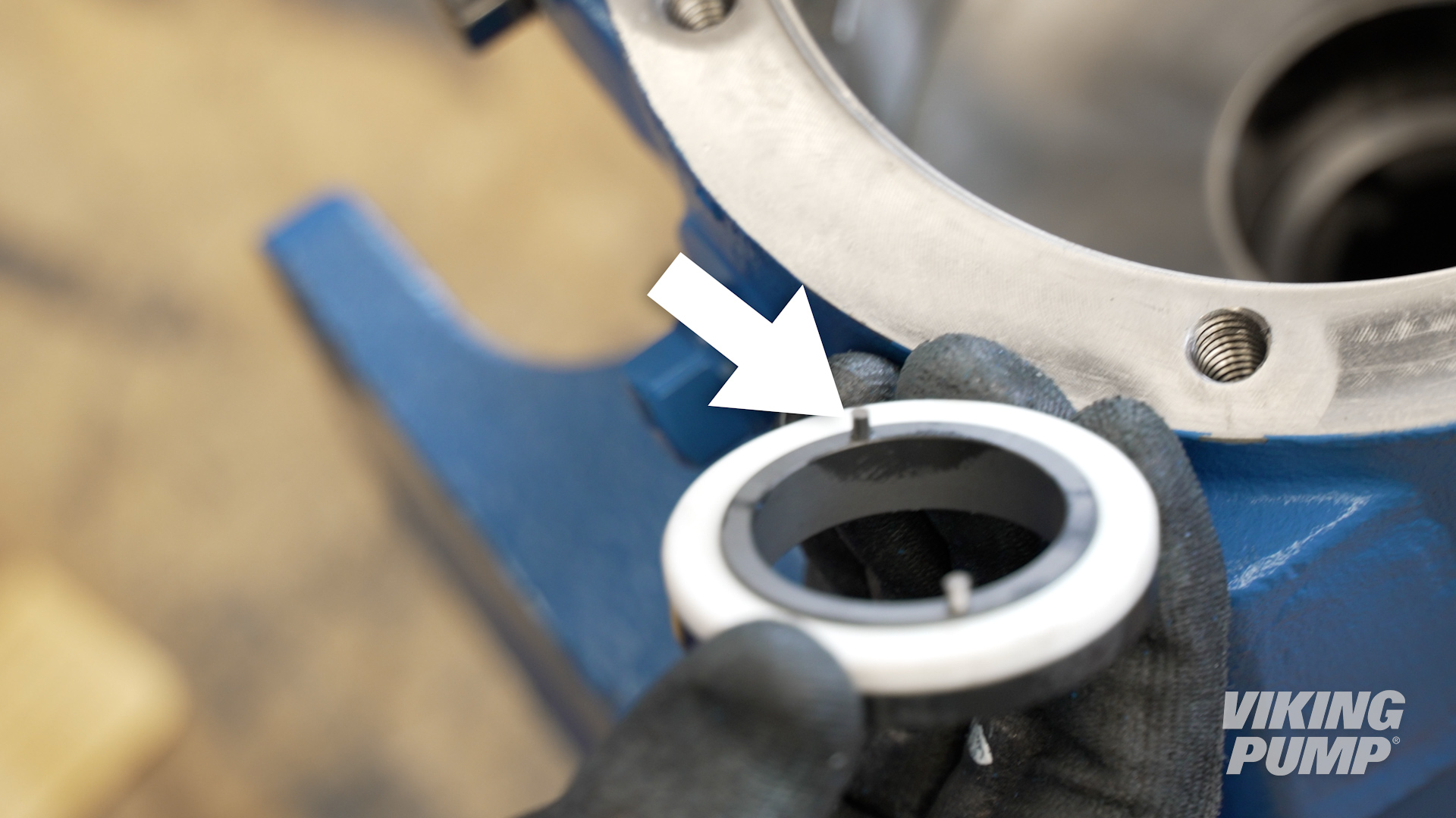
| 5. Install the seal seat with the pins down and aligned with the grooves in the bushing. Carefully push the seal until it is fully seated against the seal spacer. |
|
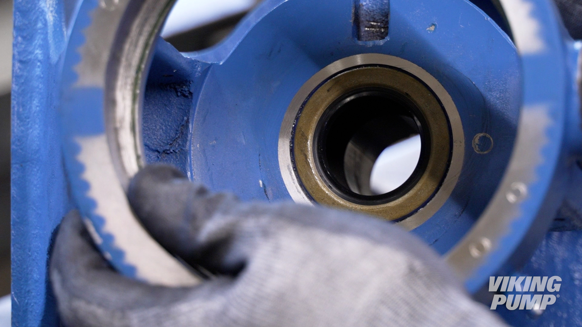
| 6. Tape the threads on the shaft before installing to prevent damage to the bracket lip seal. Lubricate then install. |  |
| 7. Remove the tape and seal installation sleeve. | |
| 8. At this point, the seal is engaged and pushing the rotor/shaft out of the pump, the bearing housing will need to be installed to aid with head installation. | |
| 9. Reinstall the half-round rings, bearing spacer collar, bearing housing, lock washer, and locknut. Fully tighten the locknut. | |
| 10. Loosen the bearing housing to open the clearance and pull the rotor into the casing. Use caution when turning the bearing housing and stop if you encounter resistance to avoid over-compressing the seal. | |
| 11. Install the head gasket and idler onto the pump, then install the head onto the casing. | |
| 12. Set the end clearance. | |
| 13. Finally, grease the bracket with application appropriate grease. Continue to pump in grease until grease begins to exit the relief fitting. Make sure to rotate the pump while greasing. | 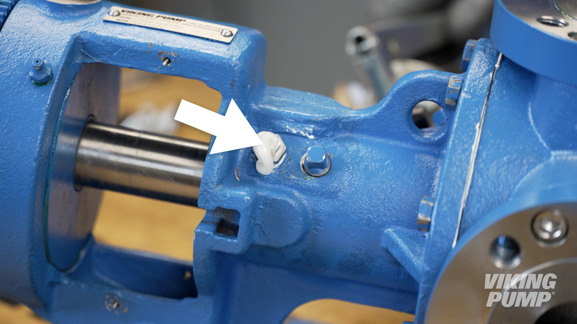 |


March 25, 2025

February 21, 2025
December 04, 2024