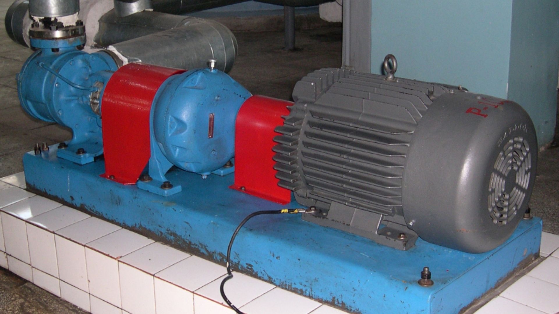
In the world of positive displacement pumping, reduced speed operation is a common requirement. High viscosity liquids, shear sensitive liquids, abrasive liquids, or any combination thereof require the pump speed to be reduced from synchronous motor speeds.

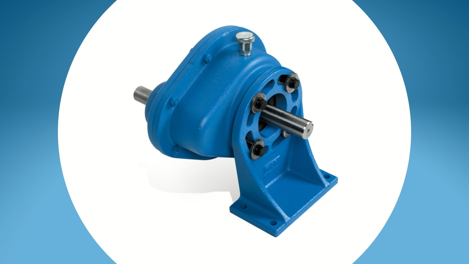
One of the simplest solutions to this is a gear reducer. These simple machines consist of one or more pairs of gears. The driver (typically an electric motor) turns the smaller gear at high speed. The smaller gear (drive gear) rotates a larger gear (driven gear) with a greater number of teeth. The ratio of driven gear teeth to drive gear teeth determines the ratio of the gear reducer. As an example, a reducer with a 10-tooth drive gear and 30-tooth driven gear has a ratio of 3:1. The speed of the output shaft (and connected pump) would be 1/3 that of the driver shaft (and connected motor).
Gear reducers are simple, reliable, and highly efficient. So what’s the downside? There are a few:
- An additional piece of equipment means extra cost added to the purchase price of the unit.
- An additional piece of equipment also means added length and weight to the overall pump unit.
- Gear reducers are typically oil lubricated which means the oil condition should be monitored and the oil needs to be periodically replaced.
These counterpoints can lead some to look for other options to reduce the speed of their pump. One way to address all three is to reduce the speed of the motor and one of the most common ways to do that is to use a VFD (variable frequency drive). Is it possible to just remove the gear reducer and use an AC motor with a VFD drive? The short answer is yes, but to do so requires oversizing of the motor to the application and depending on the speed reduction required may be a more expensive and larger overall size solution after all.
“Why?”
Let’s think of the gear reducer in another way. Think of the gear reducer as a torque converter. Power in = Power out.
On the input side, the speed is high / the torque is low.
On the output side, the speed is low / the torque high.

As a result, the coupling on that low speed / high torque side between the reducer and the pump is larger and capable of transferring higher torque.
The reducer allows us to run a low speed / high torque load (the pump) with a low torque / high speed motor.
So what happens if we remove our “torque converter” and just run the pump directly from the motor via a VFD?
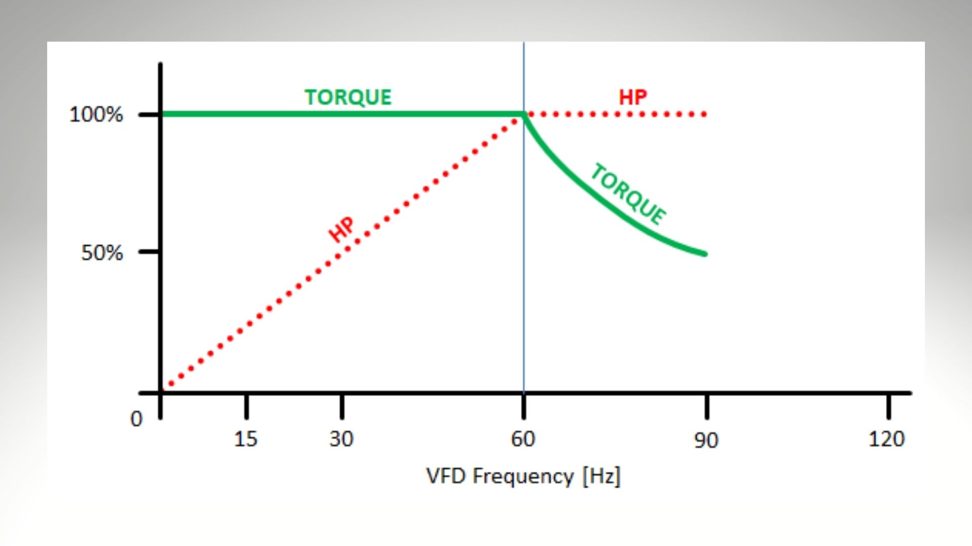
As you’re likely aware, motors run with VFD’s provide constant torque. This can lead customers to an incorrect conclusion that they provide constant HP. Let’s look at the basic torque equation:
Torque = [Power x constant] / Speed
If we decrease the speed, but torque is constant, then power available decreases. In other words, if a motor is running at half speed (via the VFD) it is capable of only half its rated power. Below is a chart to help explain this.

As an example, let’s consider an application where the desired pump speed is 600 RPM and the required power is 10 BHP.
Option 1, using a Gear Reducer:
Using a 4-pole, 60 Hz (approximately 1800 RPM) motor and the 3:1 ratio gear reducer described above the pump speed would be 600 RPM and require a 10 HP motor.
Option 2, using just a motor and VFD drive:
Using a 4-pole, 60 Hz (approximately 1800 RPM) motor and lowering the frequency to 20 Hz the pump speed would be 600 RPM. But running at 1/3 of its synchronous speed it has only 1/3 of its rated power available or approx. 3.3 HP. This is not enough power available to run the example pump at these conditions. This means that the motor size must be increased to 30 HP (synchronous rating) to have 10 HP available when running at 1/3 it synchronous speed.
This larger motor means extra cost, size, and weight, and nullifies much of the rationale for omitting the gear reducer. For slight reductions in speed (or a desire to easily vary the speed) a VFD is a great option to consider. But for considerable reductions in speed a gear reducer is a better option.

And there are other options to reduce the size of the unit while still using a gear reducer; gear motors, c-flange mounted reducers, and right-angle bevel or worm gear drives have all been used to reduce unit sizes while still utilizing gear reducer drives. So don’t fear the gear reducer! These simple machines are still the best and most reliable option when reduced speed is needed for a pumping application.