If you’ve ever fallen asleep reading pump texts about NPSH, you’re not alone. But here’s an easy-to-understand, graphical approach to ensuring your NPSHa>NPSHr.
For newbies, Net Positive Suction Head Available (NPSHa, a function of the suction side of the pump system) must exceed Net Positive Suction Head Required (NPSHr, a function of the pump) to avoid cavitation which results in pump damage. We’ll also discuss ways to adjust the variables to maximize NPSHa for both new and existing installations.
Traditionally we would use the equation NPSHa = Ha ± Hz – Hf – Hvp, where
- Ha = absolute pressure on the surface of the liquid in the supply tank (a.k.a. atmospheric pressure at the site’s altitude above sea level).
- Hz = vertical distance from the surface of the liquid in the supply tank to the centerline of the pump suction port. If the liquid is below the pump centerline, Hz is negative.
- Hf = friction losses in suction piping.
- Hvp = absolute vapor pressure of liquid at pumping temperature.
Remember! All H (Head) values must be expressed in the same units, whether feet or meters of liquid pumped.
Another more visual way to look at it is to plot the absolute pressure Ha against the sum of the other four variables, in the graphic solutions shown below in Figs. 1 & 6. In the first example we want to top-unload tank trucks of hot toluene with a pump mounted above the truck, so we are trying to determine the maximum allowable suction lift Hz. The same graphical solution can be used to find maximum values for any of the other variables as well: suction friction losses Hf, vapor pressure Hvp or to help select a pump with an allowable NPSHr value. Take a minute to look at the graphic, then read on to get more detail on where the numbers come from.
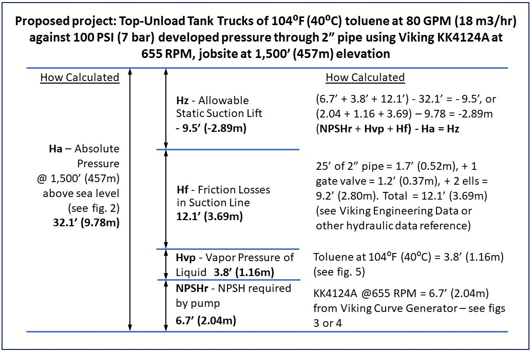
In this case we start on the left with the variable that is most difficult to change: Ha, or absolute pressure, because the pump’s site location is where it is. Another way to think of Ha is that it is the maximum height of water that could be forced up a long vertical pipe by atmospheric pressure on the source reservoir, with a perfect vacuum at the top of the pipe. This project is located at a site 1,500 feet (457m) above sea level with source tank open to atmosphere, which provides 32.1 feet (9.78m) of head from atmospheric pressure to force liquid into the pump’s suction when primed. For your site, refer to the table in Fig. 2 to get the feet or meters of head for Ha.
| Pressure vs Altitude | |||||
| Altitude | Barometric Pressure | Head | |||
| Feet | Meter | PSI | Bar | Feet | Meter |
| 0 | 0 | 14.7 | 1.00 | 33.92 | 10.34 |
| 500 | 152 | 14.43 | 0.98 | 33.29 | 10.15 |
| 1,000 | 305 | 14.16 | 0.96 | 32.67 | 9.96 |
| 1,500 | 457 | 13.91 | 0.95 | 32.09 | 9.78 |
| 2,000 | 610 | 13.66 | 0.93 | 31.52 | 9.61 |
| 2,500 | 762 | 13.41 | 0.91 | 30.94 | 9.43 |
| 3,000 | 914 | 13.17 | 0.90 | 30.39 | 9.26 |
| 3,500 | 1,067 | 12.93 | 0.88 | 29.83 | 9.09 |
| 4,000 | 1,219 | 12.69 | 0.86 | 29.28 | 8.92 |
| 4,500 | 1,372 | 12.46 | 0.85 | 28.75 | 8.76 |
| 5,000 | 1,524 | 12.23 | 0.83 | 28.22 | 8.60 |
| 6,000 | 1,829 | 11.78 | 0.80 | 27.18 | 8.28 |
| 7,000 | 2,134 | 11.34 | 0.77 | 26.16 | 7.97 |
| 8,000 | 2,438 | 10.91 | 0.74 | 25.17 | 7.67 |
| 9,000 | 2,743 | 10.5 | 0.71 | 24.23 | 7.38 |
| 10,000 | 3,048 | 10.1 | 0.69 | 23.30 | 7.10 |
| 15,000 | 4,572 | 8.3 | 0.56 | 19.15 | 5.84 |
| 20,000 | 6,096 | 6.76 | 0.46 | 15.60 | 4.75 |
Fig 2. – Absolute Pressure (and Head Equivalent) vs. Altitude Table
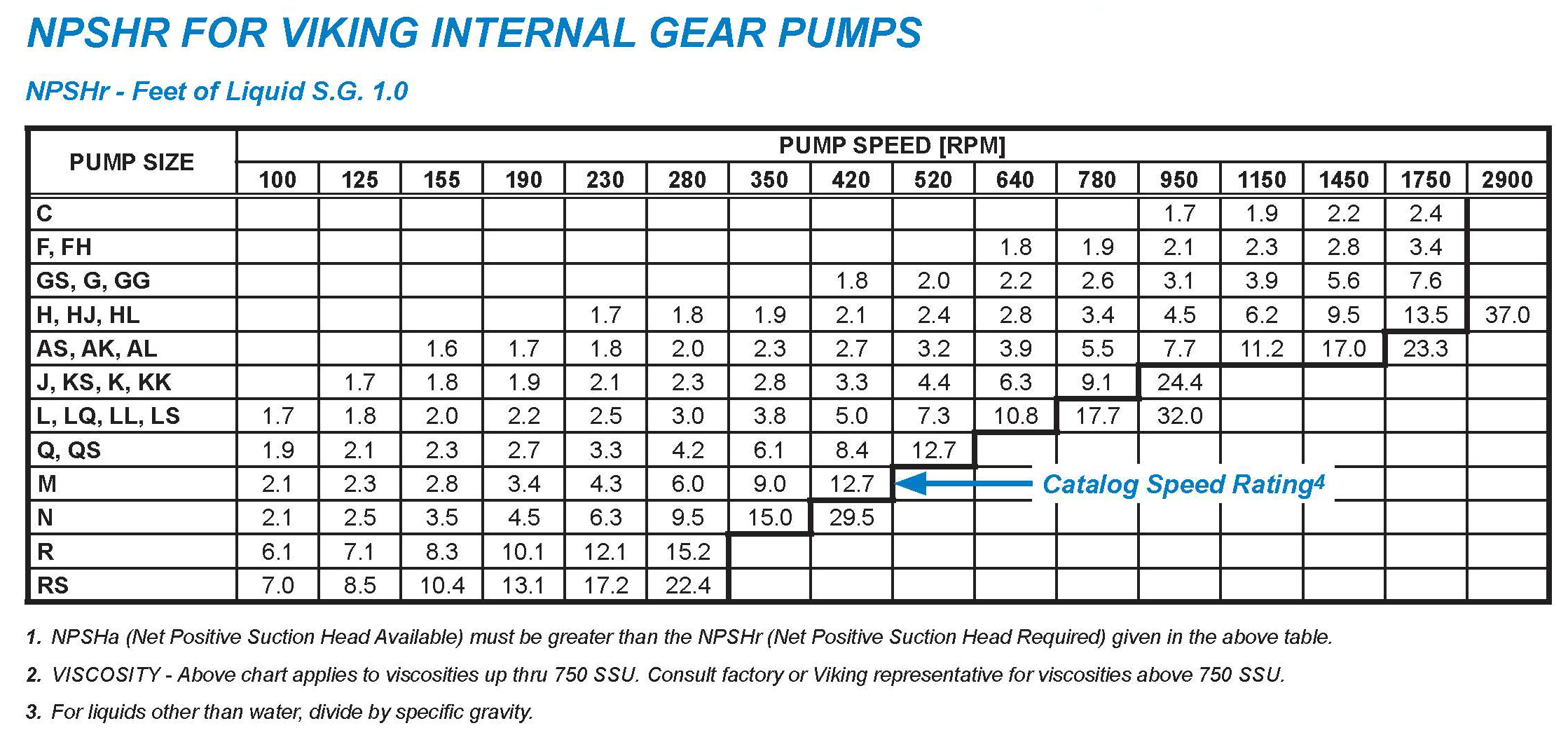
Back in Fig. 1 look to the lower right for NPSHr. This is a function of whichever pump you choose, at the desired speed. With Viking pumps, you can find NPSHr in feet or meters of head on the Viking Curve Generator, as shown on Fig. 3. For others, consult the pump manufacturer.
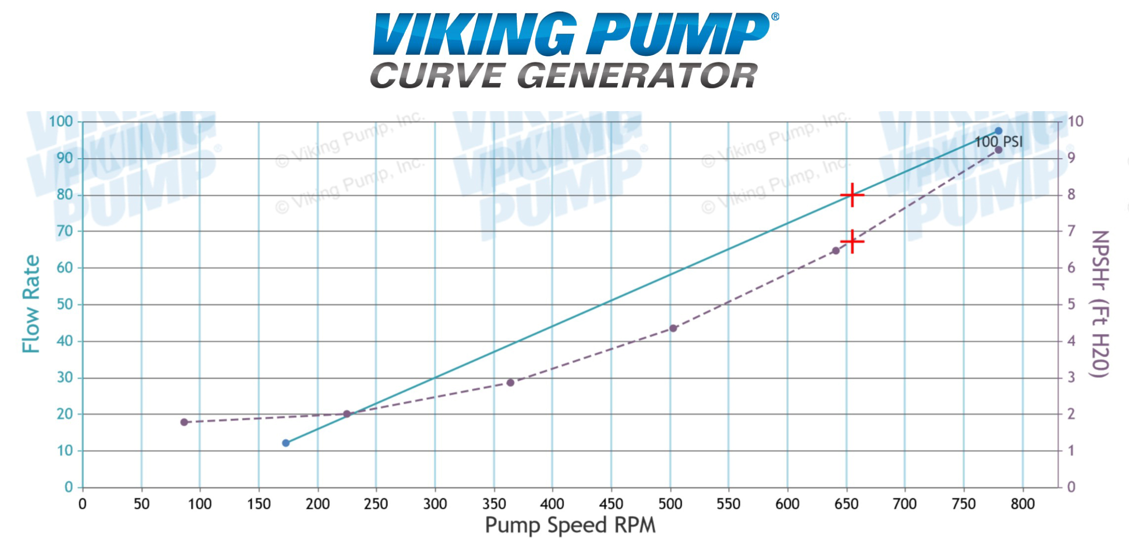
One unique advantage of Viking pumps, and PD pumps in general, is that in a cavitation situation you can reduce an existing pump’s NPSHr by simply reducing the speed, either through a Variable Frequency Drive (VFD) or by changing the gear reducer ratio. The effects of this speed reduction can be seen in Fig. 4, where reducing speed by a few hundred RPM can reduce NPSHr by several feet. That will, of course, reduce flow rate which is proportional to speed, but can be a good temporary fix until other variables can be addressed.
This also supports the common practice of selecting a larger pump and running it slower to maximize life. To get the 80 GPM (18 m3/hr) we want, we could have selected the next larger pump, an L4124A running at 390 RPM with an NPSHr of only 4.5’ (1.37m), or even the next larger model, an LL4124A at 313 RPM with 3.3’ (1.01m) NPSHr, both significantly less than the KK.
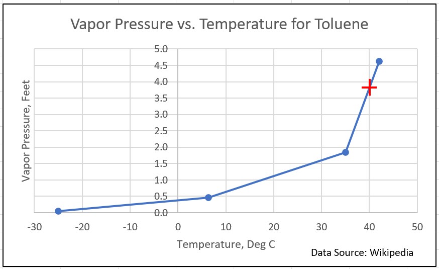
As a function of the liquid being pumped, Vapor Pressure Hvp may seem like it is fixed, but for many volatile liquids Hvp can be reduced by reducing the temperature. This can be seen in Fig. 5’s graph of Vapor Pressure vs. Temperature. This also helps explain why some pumps cavitate in summer but not in winter, if their NPSHa and NPSHr are close to being equal.
Friction losses in the suction line, Hf, can be reduced, even in existing systems, by either increasing suction pipe size, changing standard elbows to long sweep elbows, increasing the mesh size in suction strainers or changing valves to lower friction loss designs (e.g. globe valve to gate valve). Moving the pump to be closer to the source tank may be a last resort.
Finally Hz, the vertical distance from the surface of the liquid in the supply tank to the centerline of the pump will tell you how much suction lift, if any, is allowable to enable a pump to be located above the liquid level in the tank.
As a check, let’s plug our values from the graphical solution into the original NPSHa equation NPSHa = Ha ± Hz – Hf – Hvp. We get NPSHa = 32.1’ – 9.5’ – 12.1’ – 3.8’ = 6.7’, or 9.78m – 2.89m -3.69m - 1.16m = 2.04m, which just happen to be equal to the NPSHr values for the pump we selected, so in both approaches NPSHa=NPSHr. Note that because it is a suction lift we are subtracting Hz. If it were a positive suction head we would be adding it.
Most pump users want NPSHa to exceed NPSHr by a buffer of at least several feet to allow for changing conditions, and while the buffer is not shown in these charts or calculations, it is clearly a best practice to factor that in. So while we can pull a suction lift Hz of up to 9.5’ (2.93m), reducing that by a few feet or a meter would be optimal, or else make other adjustments to improve NPSHa like choosing the larger L or LL size pump.
How would you know if suction lift is not possible? If the sum of NPSHr + Hvp + Hf exceeds Ha, then the difference, Hz, must be positive head on the pump suction. An example of where this might occur is if you wanted to flush the same pump system with hot water between batches. On 180⁰F (82⁰C) water, Hvp is 17.8’ (5.43m). Look at that graphically below.
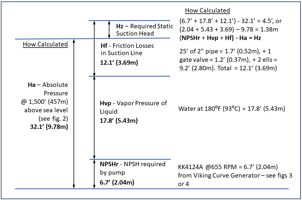
In this case the high vapor pressure of the hot water requires a minimum of 4.5’ (1.38m) of positive head on the suction side of the pump to prevent cavitation. In this case a hot water source must be located above the pump for the flush cycle.
Two last caveats 1) this brief discussion does not consider applications drawing from vessels under pressure or vacuum, and 2) it does not consider Hv, velocity head at the suction port, because it is usually negligible. Hv values for Viking Pumps can be found in Viking’s publication AD-19 “Net Positive Suction Head.”
As you’ve seen, visualizing NPSH isn’t that difficult and can either prevent or resolve cavitation issues that would result in unplanned downtime and excessive maintenance costs. Be sure to consult your local Viking Pump Authorized Distributor for assistance with new pump selection and cavitation-avoidance strategies.
Related Blogs
Relief Valves: The ever-vigilant heroes
Millions of homes around the world are fitted with water heating devices such as boilers or water supply heaters. Should they overheat, pressures can rise internally until the tank ruptures. Though extremely rare, this does happen and can even propel a water heater like a rocket through the floor and roof of a dwelling. So how can we sleep peacefully each night with the knowledge that a potential catastrophe lurks in the basement?
Pressure & Vacuum Pumping Application Concerns
In the world of gear pumps, it is common to have liquid handling applications where pressure and vacuum are of concern. So, we wanted to share our perspective and recommendations, to help with making pump choices and decisions for the various pressure and/or vacuum scenarios you may encounter.

It Flows Both Ways: a guide to running an internal gear pump in reverse
One of the biggest limitations of a traditional centrifugal pump is its inability to reverse the direction of flow. By design it can only be run in one rotation and one direction of flow. Liquid enters the eye of the impeller at the suction port (typically on the front of the pump), is pushed out radially, and exits the pump at the discharge port (typically on top of the pump). For most centrifugal pumps the suction port is larger than the discharge port to better feed liquid into the pump, and to remove any confusion as to which port is “in” and which port is “out.” Rotation arrows can be found cast onto the pump or printed on the nameplate to make it perfectly clear that these pumps run in one direction of rotation and one direction of flow.
Current and Flow: An electrical engineer’s guide to the concepts of fluid systems
Unlike most of my colleagues I didn’t start out with a mechanical background. While they were studying kinetics and machine design, I was studying digital electronics and industrial power. When I started my career in the world of pumps, I had to learn a whole new set of concepts. What was surprising was that while the terminology may be a bit different, the concepts are very similar. Think of the following as a “Rosetta Stone” for translating the common terms and concepts of fluid systems to your more familiar terms and concepts of electrical systems.
Viscosity Through Thick and Thin
Viscosity is a measure of a liquid’s resistance to flow. And you don’t need to work in a laboratory to observe this. Anyone who’s spent any time in the kitchen has observed a variety of liquids with a wide variety of viscosities.