About Us
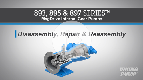
Welcome! In this video we will guide you through the disassembly and reassembly of Viking Pump’s 893, 895, and 897 Series™ mag drive internal gear pumps.
This video applies to these pump models: GG893, HJ893, HL893, AS893, AK893, AL893, GG895, HJ895, HL895, AS895, AK895, AL895, GG897, HJ897, HL897, AS897, AK897, AL897
Before you begin, please consult the appropriate technical service manual for safety information. A copy of the latest revision can be found on our website at vikingpump.com.
Warning: Rare earth magnets, like those used in the magnetic drive coupling, have extremely strong magnetic fields and are capable of changing the performance of or damaging items such as: pacemakers, metal implants, watches, computers, cellular or mobile devices, and credit cards.
Keep the pump and work area as clean as possible when working with rare earth magnets. It’s important to work on a non-magnetic surface and to keep metal tools away from the magnets.
Next, ensure the pump is secured to the work bench.
Remove the cap screws securing the pump to the magnetic coupling bracket. Pumps with the smallest “A” size magnet will have 2 cap screws, while the larger “B” or “C” sizes will have four.
Pull the pump and inner magnet from the magnetic coupling bracket.
Warning: Do not place your fingers onto the front of the pump mounting flange or face of the bracket. If the pump is not pulled out completely, it will snap back and pinch your fingers or hand.
When setting the pump or inner magnet down, be careful not to set it near any iron or steel objects which may be attracted or damaged by the magnet.
Remove the canister. Ensure to pull it straight off and use caution as it will likely be full of liquid. Drain the pump of any residual liquid by turning the shaft.
For “B” and “C” size magnets, insert a brass bar through a port between the gear teeth to prevent the shaft from rotating. Loosen and remove the cap screw and lock washer.
For “A” size magnets remove the retaining ring from the end of the shaft to remove the inner magnet.
Slide the inner magnet off of the pump shaft and remove the washer. Again, use care when setting this powerful magnet down.
If pump disassembly is required, remove the shaft key and retaining ring.
Loosen and remove the head cap screws. Remove the pump head. Be careful not to allow the idler gear to fall from the head of the pump.
Remove the idler gear from the idler pin. Make sure to keep the head gaskets as they are all required to maintain the proper end clearance.
Remove the rotor/shaft assembly.
Inspect the pump parts for wear and replace any worn components. If a new casing or balance plate bushing is required, it’s suggested to remove the balance plate by removing the two cap screws.
Inspect the casing o-ring. Remove and replace if damaged.
If removed, reinstall the balance plate.
Reinstall the rotor/shaft assembly.
Next, place the idler gear on the idler pin. Reinstall the head onto the pump, making sure to use the same thickness of gaskets.
Reinstall and tighten the head cap screws. Verify the end clearance with feeler gauges.
Replace the retaining ring and shaft key.
Next, slide the inner magnet over the shaft until it rests against the retaining ring.
Install the washer, lock washer, and cap screw at the end of the shaft. For A size magnets, there is another retaining ring.
For "B" and "C" size magnets, insert a brass bar through a port and between the gear teeth to prevent the shaft from turning - then tighten the cap screw.
Ensure the pump turns freely.
Reinstall the canister.
Next, place the pump back on the magnetic coupling bracket. Ensure that the coupling bracket is secured. Remember, do not place your fingers onto the front of the pump mounting flange or the face of the bracket. Align the canister into the bore of the bracket and gently slide in. When the magnets start to engage, the unit will finish engagement on its own very quickly. Make sure your fingers are not in front of the pump.
Finish the assembly by securing the pump to the bracket by tightening the mounting cap screws. Finally, make sure the pump rotates freely.
Your Viking Pump 893, 895, or 897 Series™ mag drive internal gear pump is fully repaired and ready to be put back into service. For more information or to view other service videos, visit our website at vikingpump.com.
Complete Service & Repair
Welcome! In this video we will guide you through the disassembly and reassembly of Viking Pump’s 893, 895, and 897 Series™ mag drive internal gear pumps.
This video applies to these pump models: GG893, HJ893, HL893, AS893, AK893, AL893, GG895, HJ895, HL895, AS895, AK895, AL895, GG897, HJ897, HL897, AS897, AK897, AL897
Before you begin, please consult the appropriate technical service manual for safety information. A copy of the latest revision can be found on our website at vikingpump.com.
Warning: Rare earth magnets, like those used in the magnetic drive coupling, have extremely strong magnetic fields and are capable of changing the performance of or damaging items such as: pacemakers, metal implants, watches, computers, cellular or mobile devices, and credit cards.
Keep the pump and work area as clean as possible when working with rare earth magnets. It’s important to work on a non-magnetic surface and to keep metal tools away from the magnets.
Next, ensure the pump is secured to the work bench.
Remove the cap screws securing the pump to the magnetic coupling bracket. Pumps with the smallest “A” size magnet will have 2 cap screws, while the larger “B” or “C” sizes will have four.
Pull the pump and inner magnet from the magnetic coupling bracket.
Warning: Do not place your fingers onto the front of the pump mounting flange or face of the bracket. If the pump is not pulled out completely, it will snap back and pinch your fingers or hand.
When setting the pump or inner magnet down, be careful not to set it near any iron or steel objects which may be attracted or damaged by the magnet.
Remove the canister. Ensure to pull it straight off and use caution as it will likely be full of liquid. Drain the pump of any residual liquid by turning the shaft.
For “B” and “C” size magnets, insert a brass bar through a port between the gear teeth to prevent the shaft from rotating. Loosen and remove the cap screw and lock washer.
For “A” size magnets remove the retaining ring from the end of the shaft to remove the inner magnet.
Slide the inner magnet off of the pump shaft and remove the washer. Again, use care when setting this powerful magnet down.
If pump disassembly is required, remove the shaft key and retaining ring.
Loosen and remove the head cap screws. Remove the pump head. Be careful not to allow the idler gear to fall from the head of the pump.
Remove the idler gear from the idler pin. Make sure to keep the head gaskets as they are all required to maintain the proper end clearance.
Remove the rotor/shaft assembly.
Inspect the pump parts for wear and replace any worn components. If a new casing or balance plate bushing is required, it’s suggested to remove the balance plate by removing the two cap screws.
Inspect the casing o-ring. Remove and replace if damaged.
If removed, reinstall the balance plate.
Reinstall the rotor/shaft assembly.
Next, place the idler gear on the idler pin. Reinstall the head onto the pump, making sure to use the same thickness of gaskets.
Reinstall and tighten the head cap screws. Verify the end clearance with feeler gauges.
Replace the retaining ring and shaft key.
Next, slide the inner magnet over the shaft until it rests against the retaining ring.
Install the washer, lock washer, and cap screw at the end of the shaft. For A size magnets, there is another retaining ring.
For "B" and "C" size magnets, insert a brass bar through a port and between the gear teeth to prevent the shaft from turning - then tighten the cap screw.
Ensure the pump turns freely.
Reinstall the canister.
Next, place the pump back on the magnetic coupling bracket. Ensure that the coupling bracket is secured. Remember, do not place your fingers onto the front of the pump mounting flange or the face of the bracket. Align the canister into the bore of the bracket and gently slide in. When the magnets start to engage, the unit will finish engagement on its own very quickly. Make sure your fingers are not in front of the pump.
Finish the assembly by securing the pump to the bracket by tightening the mounting cap screws. Finally, make sure the pump rotates freely.
Your Viking Pump 893, 895, or 897 Series™ mag drive internal gear pump is fully repaired and ready to be put back into service. For more information or to view other service videos, visit our website at vikingpump.com.
Applications

Viking Pump’s original applications started at home, right here in Iowa. This original list included asphalt, fuel oil, turpentine, linseed oil, and water but did not include one of Viking Pump’s most common applications in the state today: corn syrup. Corn syrup is a sweetener made from, you guessed it…corn, and used in a variety of foods, candies, beverages, and pet foods. Next, is Rhode Island. Bunker C has many names: Heavy Fuel Oil, Bunker Oil, #6 Fuel Oil. But whatever the name, its most common use is as a fuel for ships including oil tankers and container ships for importing and exporting freight. Rhode Island certainly isn’t the only state with high volumes of ship traffic, but a significant part of the state’s economy is tied to shipping. California is perhaps the most diverse state in terms of pump applications. They’re a leading producer of milk, fruit juices, wine, and livestock. And they’re also a leading producer of tomatoes, growing around a third of the world’s production. This means lots of opportunities for Viking pumps for ketchup, tomato paste, sauce, juice, puree, salsas, and other viscous tomato-based liquids. In West Virginia (and other states), glycol is widely pumped by Viking pumps as a heat transfer fluid, but there’s a newer use. Glycol is an excellent liquid desiccant; essentially this means it is very good at absorbing water. In West Virginia, hot glycol is used to absorb water in natural gas streams. This glycol dehydration process ensures that water is removed from the natural gas before it is put into the pipelines, preventing corrosion and freezing that could occur if left in the natural gas stream. Colorado has a diverse variety of pump markets from agricultural, to chemical, to oil and gas. While you’ll find Viking pumps in each of them, let’s highlight oil and gas, specifically the refineries. Here you’ll find Viking pumps handling many of the ancillary applications to assist in the production of fuels. One such application is the handling of sulfuric acid. Viking stainless steel vane pumps are used for handling this acid which is used in the refining of fuels. So what did you think of our list? Or did we leave off an application in your state that you’d like us to highlight? Please let us know in the comments. To learn more about these applications or to view other Pump Reports please visit our website at VikingPump.com.
Viking Pump’s original applications started at home, right here in Iowa. This original list included asphalt, fuel oil, turpentine, linseed oil, and water but did not include one of Viking Pump’s most common applications in the state today: corn syrup. Corn syrup is a sweetener made from, you guessed it…corn, and used in a variety of foods, candies, beverages, and pet foods. Next, is Rhode Island. Bunker C has many names: Heavy Fuel Oil, Bunker Oil, #6 Fuel Oil. But whatever the name, its most common use is as a fuel for ships including oil tankers and container ships for importing and exporting freight. Rhode Island certainly isn’t the only state with high volumes of ship traffic, but a significant part of the state’s economy is tied to shipping. California is perhaps the most diverse state in terms of pump applications. They’re a leading producer of milk, fruit juices, wine, and livestock. And they’re also a leading producer of tomatoes, growing around a third of the world’s production. This means lots of opportunities for Viking pumps for ketchup, tomato paste, sauce, juice, puree, salsas, and other viscous tomato-based liquids. In West Virginia (and other states), glycol is widely pumped by Viking pumps as a heat transfer fluid, but there’s a newer use. Glycol is an excellent liquid desiccant; essentially this means it is very good at absorbing water. In West Virginia, hot glycol is used to absorb water in natural gas streams. This glycol dehydration process ensures that water is removed from the natural gas before it is put into the pipelines, preventing corrosion and freezing that could occur if left in the natural gas stream. Colorado has a diverse variety of pump markets from agricultural, to chemical, to oil and gas. While you’ll find Viking pumps in each of them, let’s highlight oil and gas, specifically the refineries. Here you’ll find Viking pumps handling many of the ancillary applications to assist in the production of fuels. One such application is the handling of sulfuric acid. Viking stainless steel vane pumps are used for handling this acid which is used in the refining of fuels. So what did you think of our list? Or did we leave off an application in your state that you’d like us to highlight? Please let us know in the comments. To learn more about these applications or to view other Pump Reports please visit our website at VikingPump.com.
Viking Pump’s original applications started at home, right here in Iowa. This original list included asphalt, fuel oil, turpentine, linseed oil, and water but did not include one of Viking Pump’s most common applications in the state today: corn syrup. Corn syrup is a sweetener made from, you guessed it…corn, and used in a variety of foods, candies, beverages, and pet foods. Next, is Rhode Island. Bunker C has many names: Heavy Fuel Oil, Bunker Oil, #6 Fuel Oil. But whatever the name, its most common use is as a fuel for ships including oil tankers and container ships for importing and exporting freight. Rhode Island certainly isn’t the only state with high volumes of ship traffic, but a significant part of the state’s economy is tied to shipping. California is perhaps the most diverse state in terms of pump applications. They’re a leading producer of milk, fruit juices, wine, and livestock. And they’re also a leading producer of tomatoes, growing around a third of the world’s production. This means lots of opportunities for Viking pumps for ketchup, tomato paste, sauce, juice, puree, salsas, and other viscous tomato-based liquids. In West Virginia (and other states), glycol is widely pumped by Viking pumps as a heat transfer fluid, but there’s a newer use. Glycol is an excellent liquid desiccant; essentially this means it is very good at absorbing water. In West Virginia, hot glycol is used to absorb water in natural gas streams. This glycol dehydration process ensures that water is removed from the natural gas before it is put into the pipelines, preventing corrosion and freezing that could occur if left in the natural gas stream. Colorado has a diverse variety of pump markets from agricultural, to chemical, to oil and gas. While you’ll find Viking pumps in each of them, let’s highlight oil and gas, specifically the refineries. Here you’ll find Viking pumps handling many of the ancillary applications to assist in the production of fuels. One such application is the handling of sulfuric acid. Viking stainless steel vane pumps are used for handling this acid which is used in the refining of fuels. So what did you think of our list? Or did we leave off an application in your state that you’d like us to highlight? Please let us know in the comments. To learn more about these applications or to view other Pump Reports please visit our website at VikingPump.com.
Featured Products
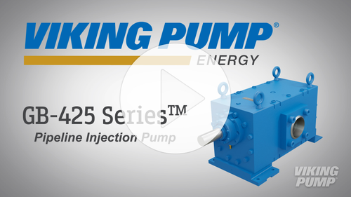
Viking Pump's GB-425 Series™ is a robust and rebuildable external gear pump that is specifically designed for pipeline injection.
Viking Pump is proud to bring you the new GB-425 Series™ pipeline injection pump. This robust, rebuildable external gear pump is specifically designed to handle the pressures, flow requirements, and abrasives that make crude oil pipeline injection one of the the most difficult applications.
With flow rates up to 25,000 barrels per day and pressure capabilities up to 1,500 PSI, this pump can handle the toughest process requirements. And a number of other features make this pump the ideal solution for pipeline injection.
The GB-425 Series™ features new internal components that have an extremely durable coating…a simple, rebuildabe design…a robust mechanical seal…and a renewed focus on efficiency and environmental impact.
This series utilizes the same durable coating on the gears and bushing blocks that has been used on both the GB-410 and GB-414 Series™. This coating protects internal components from the effects of abrasive wear - extending the life of the pump and minimizing downtime.
After receiving customer feedback, Viking Pump pursued the creation of an upgraded - rebuildable - pipeline injection pump. The GB-425 Series™ features a stacked design that allows for quick disassembly and replacement of components. By having rebuild kits on hand, pumps can be removed from service, repaired, and back online much faster than ordering a new unit. This approach not only saves time - but is a huge cost savings opportunity.
A robust mechanical seal is standard on every pump. This seal helps to prevent leakage and can withstand the high pressures required in pipeline injection.
Because of these efforts to improve pump performance - the GB-425 Series™ carries a much smaller environmental footprint than competitor technologies. This series is driven by an electric motor - which is much cleaner option. Other designs, waste motive gas, flare off CO2, or vent methane - which contributes to emissions. The mechanical seal prevents leaks from entering the environment. And the overall smooth operation leads to less strain on the system - preventing vibration and the possibility of damaging other process equipment that could lead to leaks in the system.
The GB-425 Series™ is reinventing pipeline injection and improving efficiency in a number of areas in the process. And the rebuildable design has given even more control customers in the field.