Why some pumps don’t require pressure relief valves, and some pumps do
For kinetic pumps like centrifugal and turbine pumps, flow rate will change greatly with changes in discharge head (pressure). As head increases, flow rate decreases and can eventually decrease to zero, a point called shut off head or deadhead (see fig.1). For this reason, kinetic pumps may not require overpressure protection, though it may still be used. Most air operated positive displacement pumps, including most Air-Operated Double Diaphragm (AODD) pumps, can also be safely deadheaded without overpressure protection because the maximum discharge pressure cannot exceed the air inlet pressure, usually 7 bar (100 PSI) or less.
For rotary positive displacement pumps like gear, vane, and lobe pumps, flow rate is largely independent of differential pressure (see fig. 1). A fixed volume of liquid is moved into the discharge piping with every revolution of the shaft (see fig. 2). A key advantage of these pumps is providing consistent flow regardless of changes in liquid viscosity or differential pressure. But should a downstream blockage occur, pressure will rapidly build and may exceed the rating of the pump, drive equipment, system, or any combination thereof, with the potential for damage and unplanned downtime. For this reason, overpressure protection must be used, and pressure relief valves are the most commonly used form of overpressure protection for rotary positive displacement pumps.
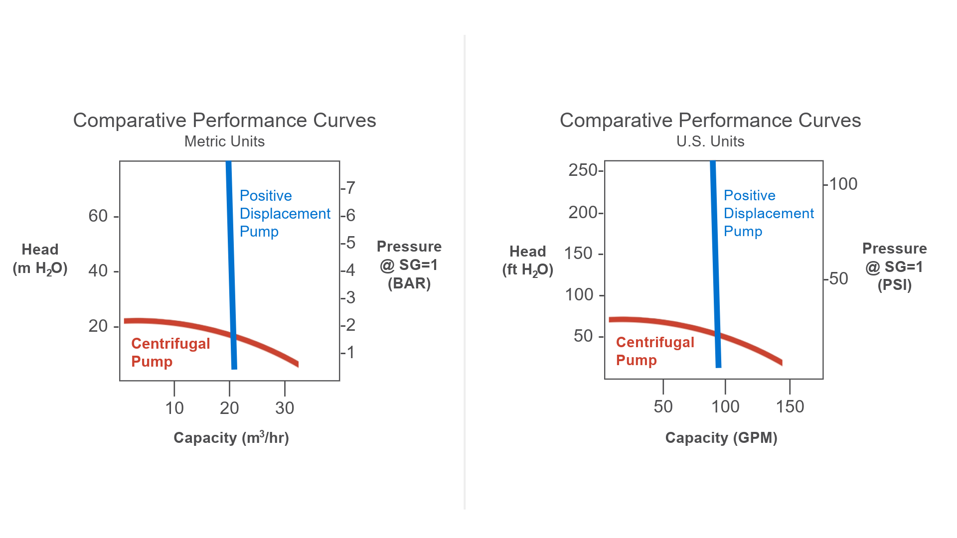
Figure 1 – Performance curves comparing rotary positive displacement and centrifugal pumps
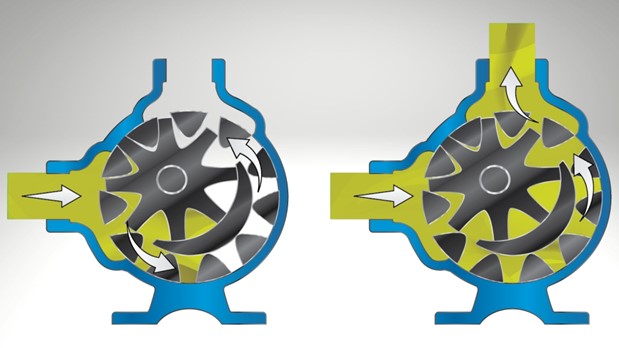
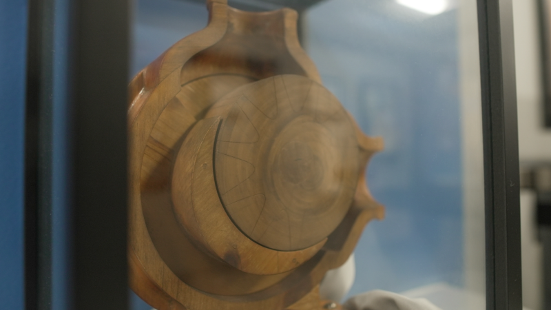
Figure 2 – Operation of an internal gear pump, a common type of rotary positive displacement pump
Relief Valve Operation
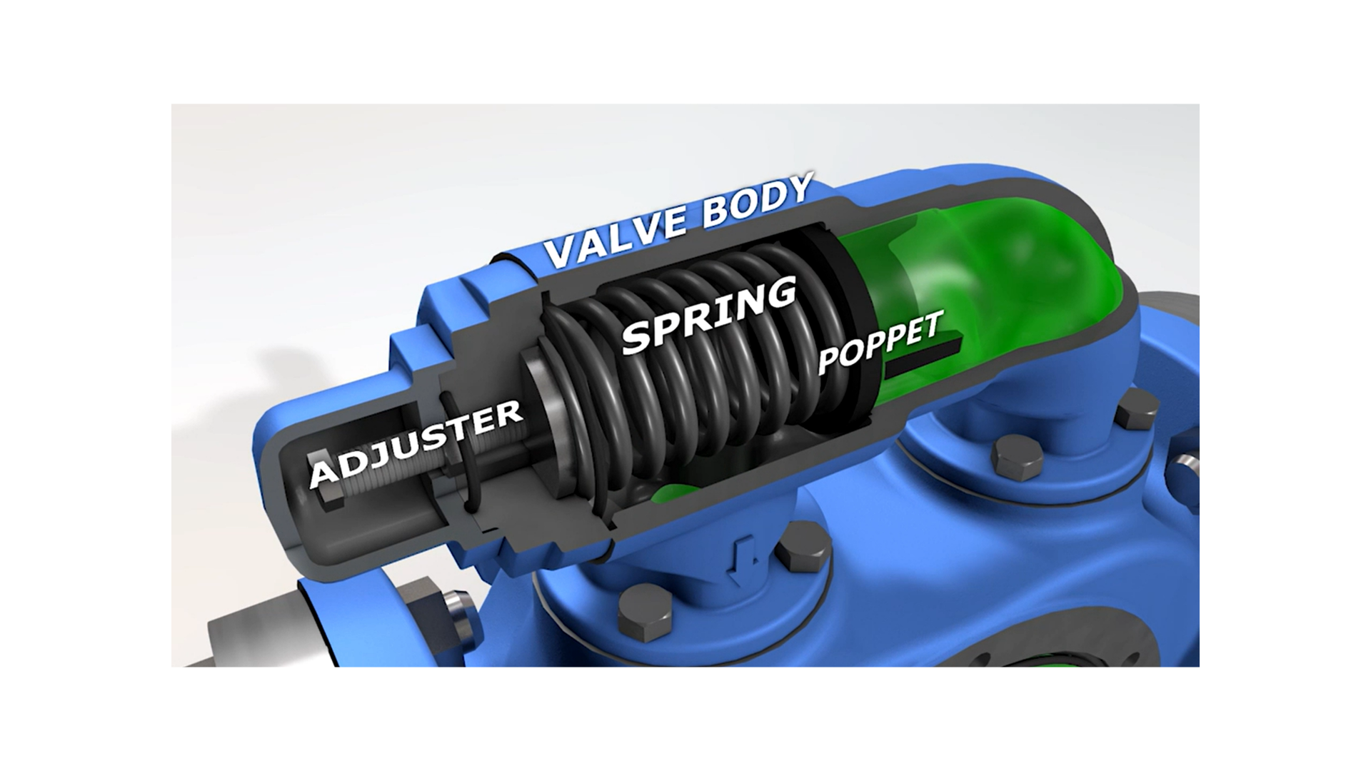
While there are other types, the most common pump relief valve utilizes a spring and moving poppet (see fig. 3). Under normal pressure, the spring holds the poppet against a machined seat, preventing liquid from bypassing. As pressure builds, eventually overcoming the spring force, the valve opens to bypass a portion of the flow. Eventually pressure may build to the point of opening the valve completely to bypass 100% of the pump’s flow. This point is called complete or full bypass pressure. As pressure returns to normal the spring closes the poppet and pump output flow returns to normal. An adjusting screw allows for adjustments to the compression of the spring to change the valve pressure setting.
IMPORTANT NOTE: This information pertains specifically to Viking Pumps and while it may be applicable to others, not all manufacturers’ relief valves would operate the same way. Some use fixed setting valves, valves may not be full ported to allow for full bypass, and some require the pump to be completely shut off to close the valve once opened. These are all important things to check with the manufacturer.
Types of Relief Valves
There are 3 common types of relief valves used with Viking Pumps. While similar in operation, they differ in how they mount into the pump system and where they divert the bypassed flow to.
The first and most common is the Internal Relief Valve. These are either attached to, or built into, the pump and require no additional piping. If differential pressure increases to the point of opening the valve, flow bypasses internally from the higher-pressure outlet side of the pump back to the lower pressure inlet side. An adjusting screw and cap can be found pointing towards the inlet side of the pump (see fig. 4). If the direction of flow were reversed and the top port was the inlet port, then the relief valve would need to be removed and reversed as well. The casing may also be rotated to different positions, so it is important to ensure that the relief valve is pointed towards the inlet port.

Internal relief valves are compact and require no additional steps to install, however it can be difficult to identify when they are in bypass which can result in heating of the liquid if run in full bypass at higher pressures or for long durations. Note that when pumping materials that are only liquid at elevated temperatures, such as bitumen, jacketed relief valves heated by steam or heat transfer fluids may be required to provide reliable pressure relief.
An alternative to the internal relief valve is the Return-To-Tank Relief Valve (see fig. 5). These valves operate just like the internal relief valve, but bypassed flow is directed back to the supply tank or a point on the inlet piping via pipes or hoses. While they do require additional piping, they can be piped in a way to observe whether they are in bypass and they carry heat way from the pump. For this reason, they are standard on Viking Pump’s 4924A Series™ Refrigeration Ammonia Pumps (see fig. 6).
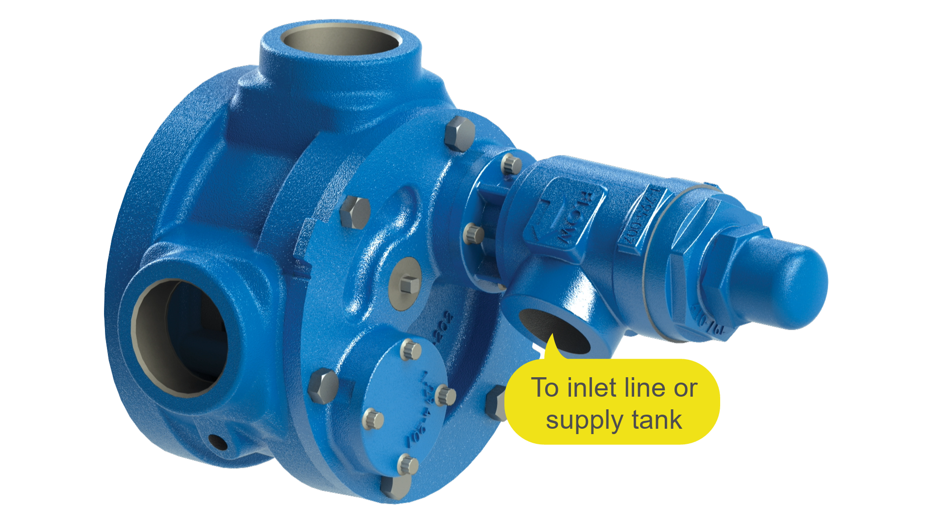
Figure 5 – Return-to-tank relief valve mounted to the head of an internal gear pump
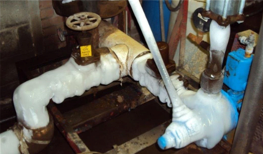
Figure 6 - Viking KK4924A refrigeration ammonia pump fitted with return-to-tank relief valve
Lastly are Inline Relief Valves (or System Relief Valves) (see fig. 7). These valves would be installed in the downstream piping and like the return-to-tank relief valve, require piping to direct any bypassed flow to the supply tank or to a point on the inlet piping. These valves are favored when frequent bypass is required and are often used in conjunction with one of the other valve options, because a pump-mounted valve is there to protect the pump, and a system valve is often there to protect against exceeding maximum system pressure downstream of the pump. It’s important to remember not to include any isolation valves between the pump and a system relief valve as this introduces opportunity to overpressure the pump. If this is necessary, then a relief valve on the pump will be required. Return-to-tank valves, whether pump-mounted or in the discharge line, may be required when handling flammable liquids because a pump with internal relief valve, when deadheaded, could develop sufficient heat to exceed the liquid’s flash point.
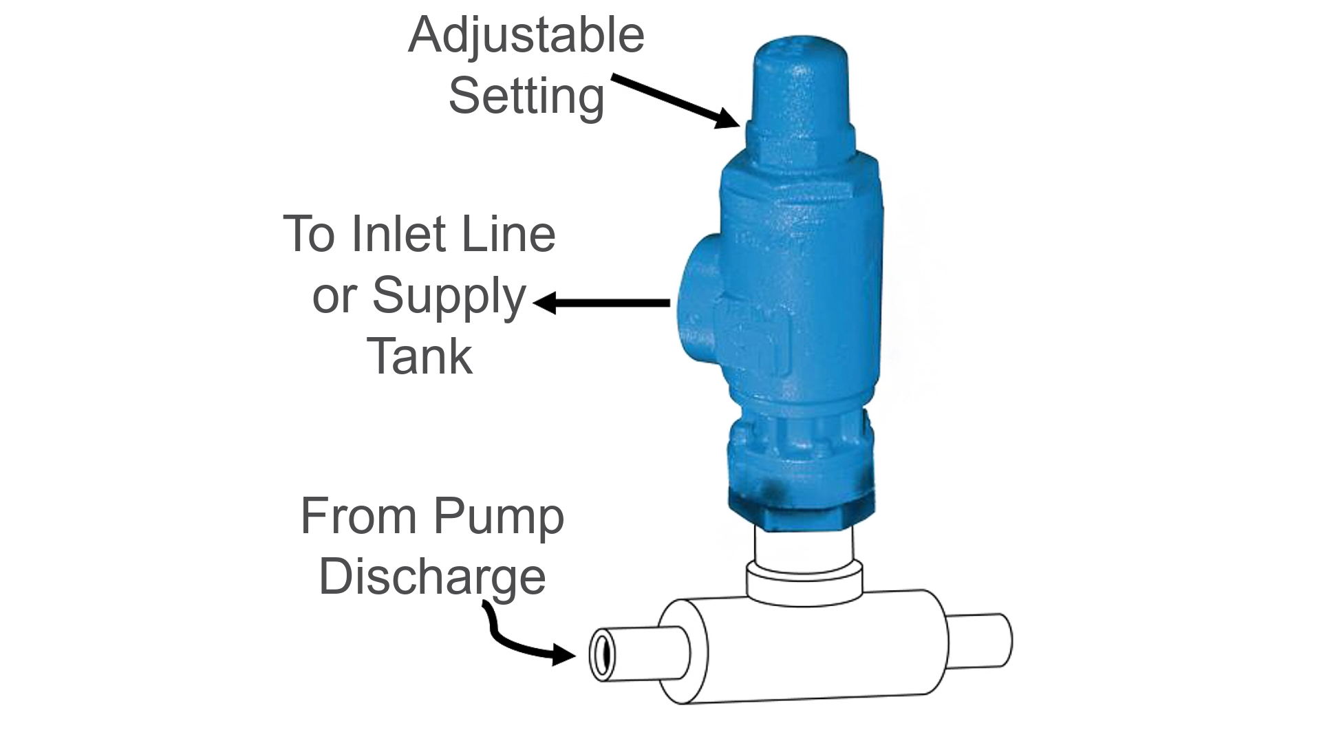
Figure 7 – In-line pressure relief valve installed in discharge pipe
The Perfect Valve is One that’s Never Used
In an ideal system overpressure should never occur and the relief valve is never called into action. Pressure relief valves are not “flow control valves” nor are they “pressure regulators.” They are there only to prevent system overpressure should an upset condition occur.
It’s best practice to have multiple means of overpressure protection. These may include, but not be limited to rupture discs, pressure transmitters and controllers, torque limiting devices, and motor overload protection devices.
Many Viking pumps have run for decades without the valve or other overpressure protection ever being called into service. However their inclusion in the pump system is essential to preventing serious, or even dangerous failures should an upset condition occur. While often overlooked, the pressure relief valve is a critical component of every rotary positive displacement pump and system.
ABOUT THE AUTHOR
John Hall has held marketing, sales, and technical management roles for several pump manufacturers, including 23 years at Viking Pump before retiring in 2023. He holds a B.S. in Technical Communications and an MBA in Marketing Management from the University of Minnesota.