Types of Positive Displacement Pumps
All positive displacement pumps work by first expanding a cavity between the casing and one or more moving parts to create a partial vacuum, so atmospheric pressure can force liquid into the pumping chamber through the inlet port. Then the pump collapses that cavity to displace the liquid through the discharge port.
There are two types of positive displacement pumps:
- Reciprocating pumps operate when a back-and-forth movement of a piston, plunger or diaphragm first causes a suction stroke to draw liquid through a check (one-way) valve to fill the fluid chamber, then a discharge stroke forces liquid out through a second check valve. Each time this cycle happens it creates a pressure spike causing pulsating flow.
- In a rotary positive displacement pump, two or more rotating members create and then collapse cavities between them and the pump casing, continuously drawing in and discharging fluid, causing smooth flow with minimal pulsation, or laminar flow.
Internal gear pumps are a type of rotary positive displacement pump. So that leaves just one question...
How Does an Internal Gear Pump Work?
If you have looked at cutaway images or animations of rotary internal gear pumps and wondered “how does that work?”, you’re not alone. While an extremely simple concept, the internal gear pumping principle does not lend itself to being understood quite as easily as the rotary external gear principle. This is because, instead of having parallel shafts with counter-rotating, intermeshing gears, its two shafts are mounted on opposite sides of the two gears, and the two intermeshing gears are turning in the same direction. Comparing these technologies will help in understanding how internal gear pumps work.
In an external gear pump, liquid is transported in the spaces between the gear teeth along the casing and then forced out the discharge port when the gear teeth mesh. Each gear is mounted on a rotating shaft, one (the drive gear) being driven by a motor or other source, the other (driven gear, or idler gear) is turned by the drive gear.
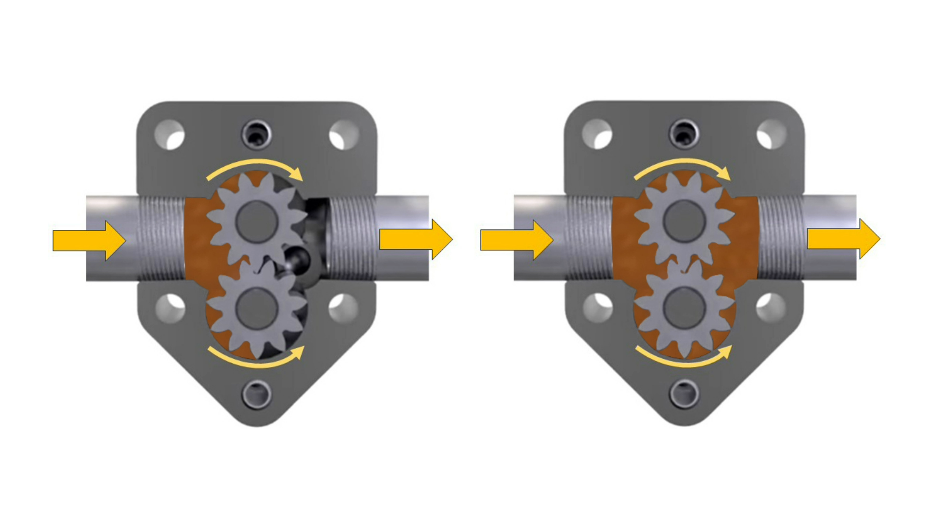
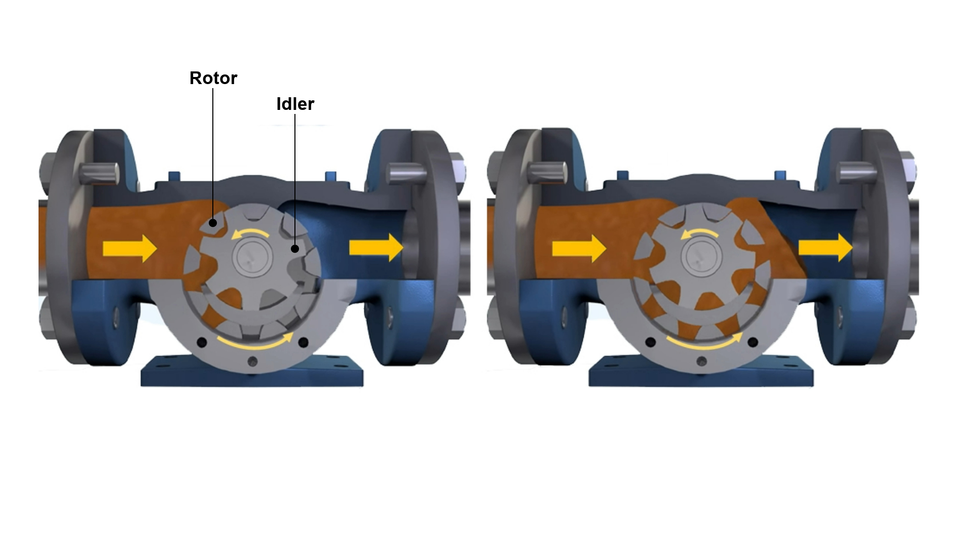
An internal gear pump rotor (outer gear) is mounted to a rotating shaft and is driven by a motor or other source. The idler (inner gear) is mounted to a fixed shaft (idler pin) on the pump’s head (front cover plate) and is driven by the rotor gear. The crescent on the pump head separates the gears so they create two flow paths which then re-join as the gears mesh, forcing liquid out of the discharge port.
Internal Components of an Internal Gear Pump
The images above still don't tell the complete story of an internal gear pump. That can be better demonstrated with a side view, as shown in the exploded diagram below.
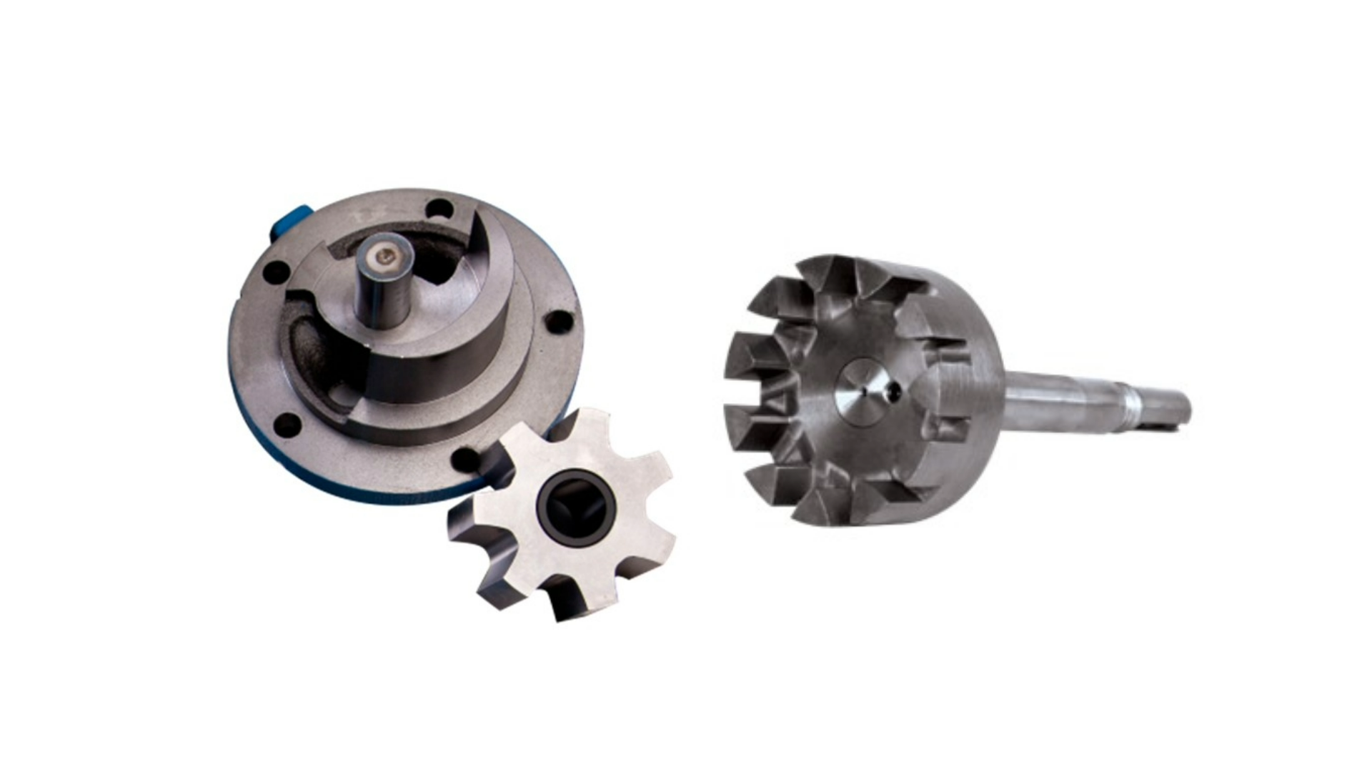
Here you can clearly see how the idler gear fits into the extended teeth of the rotor gear, and how the idler with sleeve bearing is mounted on the idler pin. Combined, this becomes part of the pump head along with the crescent which separates the two flow paths.
Once the idler is mounted on the pin, the head is mounted and fastened to the casing with the idler teeth fitting in between the rotor teeth.
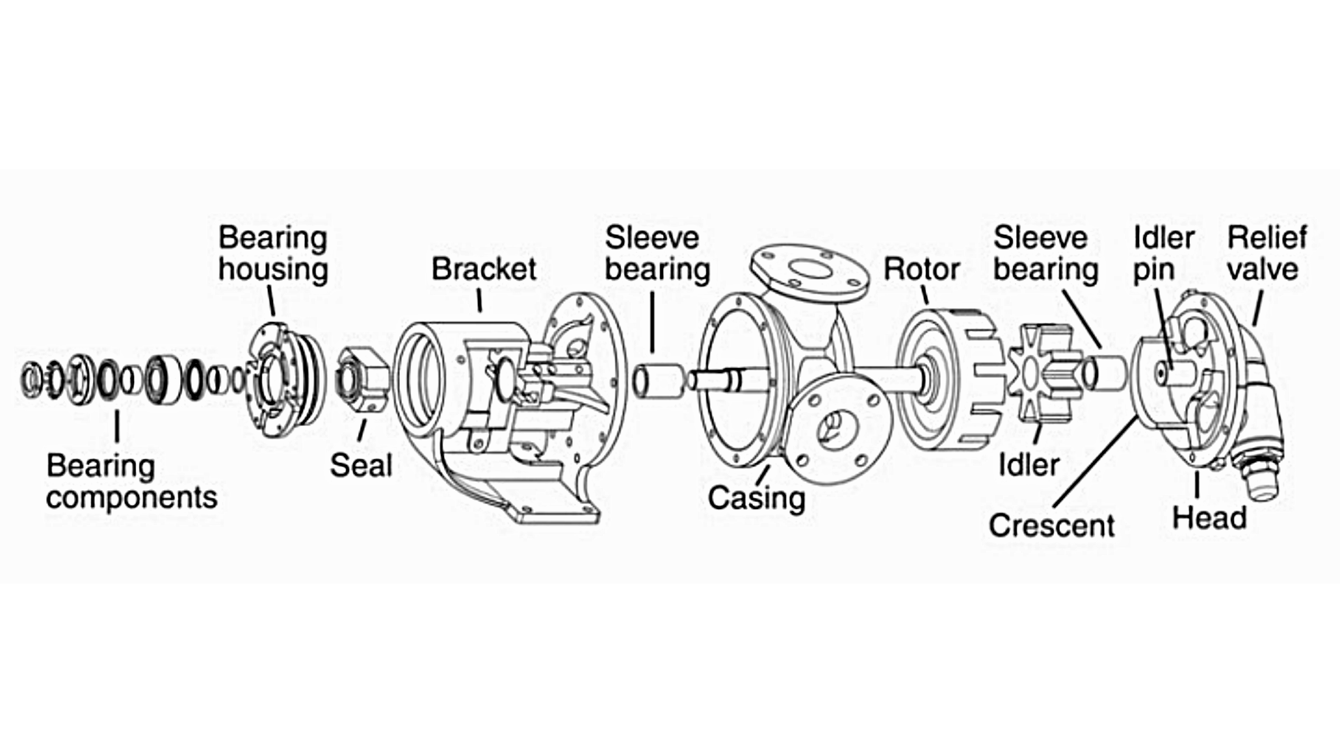
Note how the rotor/shaft assembly extends through the bracket, seal and bearing housing. The rotating shaft is supported by a sleeve bearing toward the rotor end and an antifriction bearing toward the driver end. A shaft seal mounted to the bracket prevents liquid from escaping along the rotating shaft.
As the idler gear is positioned within the interior of the rotor gear, internal gear pumps are also commonly known as “gear within a gear” pumps. This clever and unique positive displacement pumping principle was invented to dewater a quarry by Jens Nielsen, who founded the Viking Pump Company in 1911. While hundreds of variations on the design have been developed by others for different applications like automotive and aerospace, Viking Pump remains the global leader in internal gear pumps for industrial process applications.
Advantages of the Internal Gear Pump
Internal gear pumps are versatile and efficient devices that offer numerous advantages in various industrial applications. Here are some of the key benefits of using an internal gear pump.
- High Efficiency: Internal gear pumps ensure a consistent flow rate regardless of the pressure. This results in minimal energy wastage and improved overall system performance.
- Self-Priming Capabilities: They can effortlessly evacuate air or gas from the suction line, enabling smooth and uninterrupted operation. This feature eliminates the need for manual priming and reduces downtime in the system.
- Robust Construction: Viking Pump uses a vertically integrated manufacturing process to ensure quality control on all of their internal gear pumps. This ensures longevity and reliability even in challenging applications.
- Wide Range of Viscosities: Whether it's thin liquids like solvents or viscous fluids like asphalt or molasses, internal gear pumps can efficiently handle them without compromising performance. This versatility makes them ideal for industries such as chemical processing, food and beverage, pharmaceuticals, oil and gas, and more.
- Quiet Operation: The gear design ensures smooth and silent rotation, reducing noise levels and creating a more comfortable working environment.
- Precise Flow Control: By adjusting the rotational speed, operators can easily regulate the flow rate according to specific requirements. This precision allows for accurate dosing, ensuring consistent product quality and minimizing waste.
- Low Maintenance: The simple design consists of a few moving parts, reducing the likelihood of breakdowns and the need for frequent repairs.
For an excellent animation of internal gear pump operation, view our video
--------------------------------------------------------------------
About the Author
John Hall has held marketing, sales, and technical management roles for several pump manufacturers, including 23 years at Viking Pump before retiring in 2023. He holds a B.S. in Technical Communications and an MBA in Marketing Management from the University of Minnesota.