Millions of homes around the world are fitted with water heating devices such as boilers or water supply heaters. Should they overheat, pressures can rise internally until the tank ruptures. Though extremely rare, this does happen and can even propel a water heater like a rocket through the floor and roof of a dwelling. So how can we sleep peacefully each night with the knowledge that a potential catastrophe lurks in the basement?
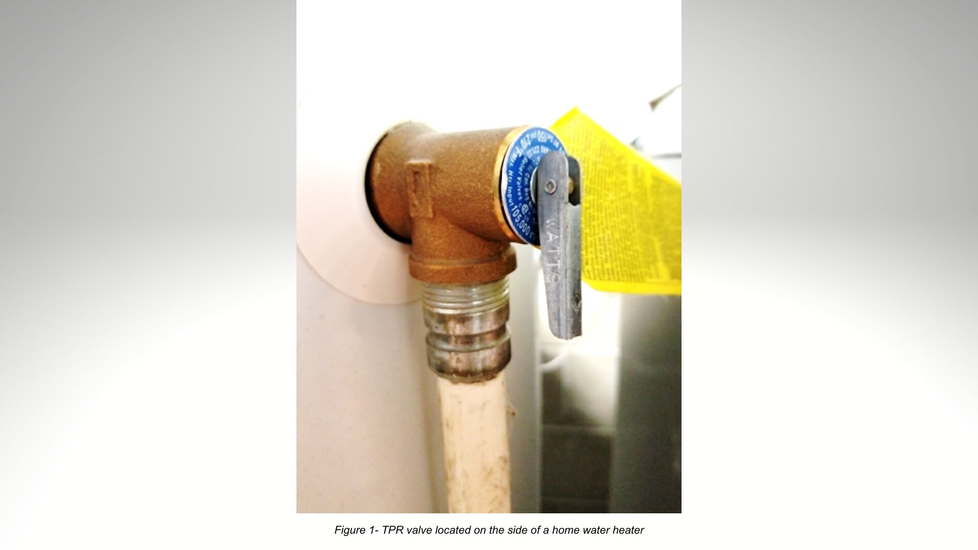
The answer lies with a small device located on the side of the tank (or sometimes the top) called a TPR (or TPRV) which stands for Temperature/Pressure Relief Valve. This spring-loaded, poppet style relief valve opens when pressure (or temperature) exceeds unsafe levels in the tank. Water is then drained from the tank to lower the internal pressure and prevent catastrophic failure. (see fig. 1)
Other than periodic testing, this valve may never open. In fact, opening of the valve should only occur if the tank’s thermostat fails as well. Similar to a building’s fire sprinkler system or the airbag in your car, the relief valve is typically idle, waiting just in case it need be called into action. But it’s also essential to prevent system failure and ensure safety.
Pumps are machines for moving liquids. As a pump moves liquid through a downstream system, pressure results. This can be due to head pressure (i.e. pushing liquid up to the top floor of a factory), friction loss through pipes and fittings, and pressure required to push liquid through other inline equipment such as meters, filters, strainers, heat exchangers, etc. The pump and associated drive equipment are sized and selected based on these typical operating conditions.
And in a perfect world that would be adequate. But in the real world variables change which can change the resulting pressure:
- Pipes and fittings may corrode or build up with solids, closing off the opening size.
- Downstream filters may clog or meters fail.
- Operators my inadvertently close downstream valves or forget to open them before turning the pump on.
In each of these scenarios, the downstream pressure will increase as a result. So how does this affect the pump? Well that depends on the pump.
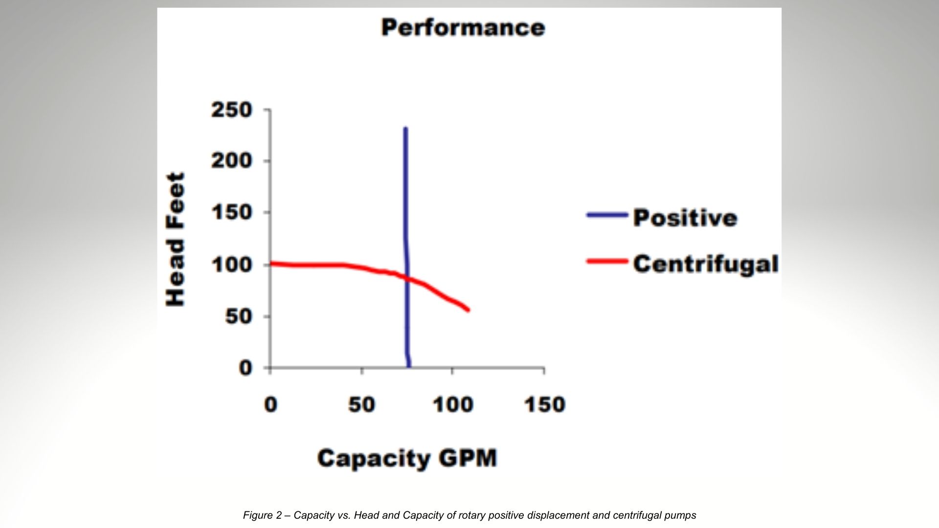
For kinetic pumps like centrifugal and turbine pumps, their flow rate changes greatly with changes in differential pressure. As pressure increases, flow rate decreases and can eventually decrease to zero (a point called shut off head or dead head) (see fig. 2). For this reason, kinetic pumps may not require overpressure protection (though it may still be used).
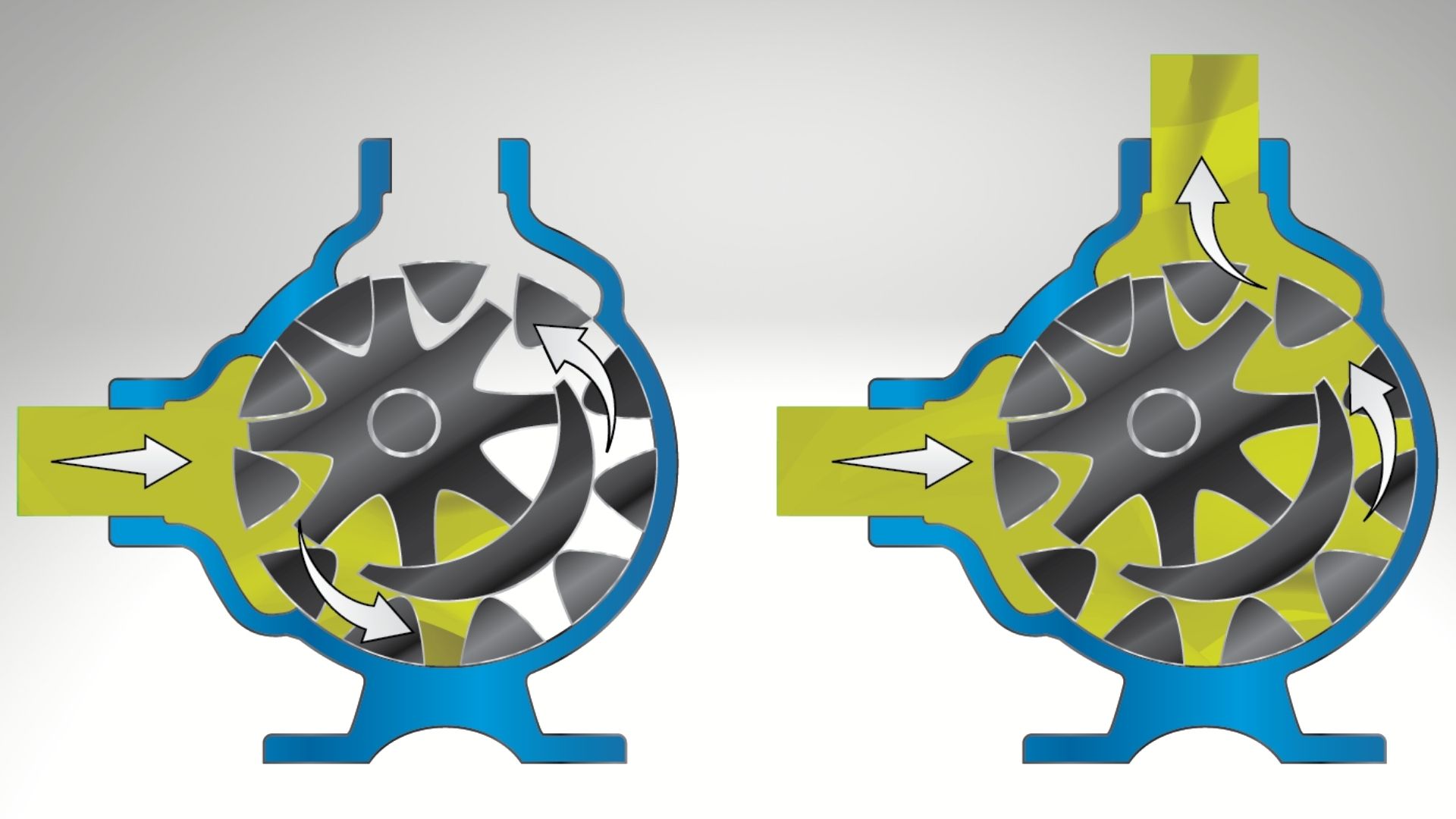
For rotary positive displacement pumps like gear, vane, and lobe pumps, their flow rate is largely independent of differential pressure (see fig. 2). These types of pumps would be considered flow generating machines. A fixed volume of liquid is moved into the discharge piping with every revolution of the shaft (see fig. 3). These pumps feature a key advantage in holding consistent flow regardless of slight changes in liquid viscosity and differential pressure. But should a downstream blockage occur as described in the examples above, pressure will rapidly build and may exceed the rating of the pump, drive equipment, system, or any combination thereof. For this reason, overpressure protection must be used. And relief valves are the most used form of overpressure protection for rotary positive displacement pumps.
While there are others, the most common pump relief valve utilizes a spring and moving poppet (see fig. 4). Under normal pressure, the spring holds the poppet against a machined seat, preventing liquid from bypassing. As pressure builds, eventually overcoming the spring force, the valve opens to bypass a portion of the flow. Eventually pressure may build to the point of opening the valve completely to bypass 100% of the pump’s flow. This point is called complete bypass pressure (or full bypass pressure). As pressure returns to normal the spring closes the poppet and pump output flow returns to normal. An adjusting screw allows for adjustments to the compression of the spring to change the valve pressure setting.
IMPORTANT NOTE: This information pertains specifically to Viking Pumps and while it may be applicable to others, not all manufacturers would comply. Some use fixed setting valves, valves may not be full ported to allow for full bypass, and some require the pump be completely shut off to close the valve once opened. These are all important things to check with the manufacturer if not using a Viking Pump relief valve.
There are 3 common types of relief valves used with Viking Pumps. While similar in operation, they differ in how they mount into the pump system and where they divert the bypassed flow to.
The first and most common is the Internal Relief Valve (see fig. 5). Internal relief valves are either attached to, or built into, the pump and require no additional piping. If differential pressure increases to the point of opening the valve, flow bypasses internally from the high pressure, outlet side of the pump back to the low pressure, inlet side. An adjusting screw and cap can be found pointing towards the low pressure inlet side of the pump (see fig. 6).
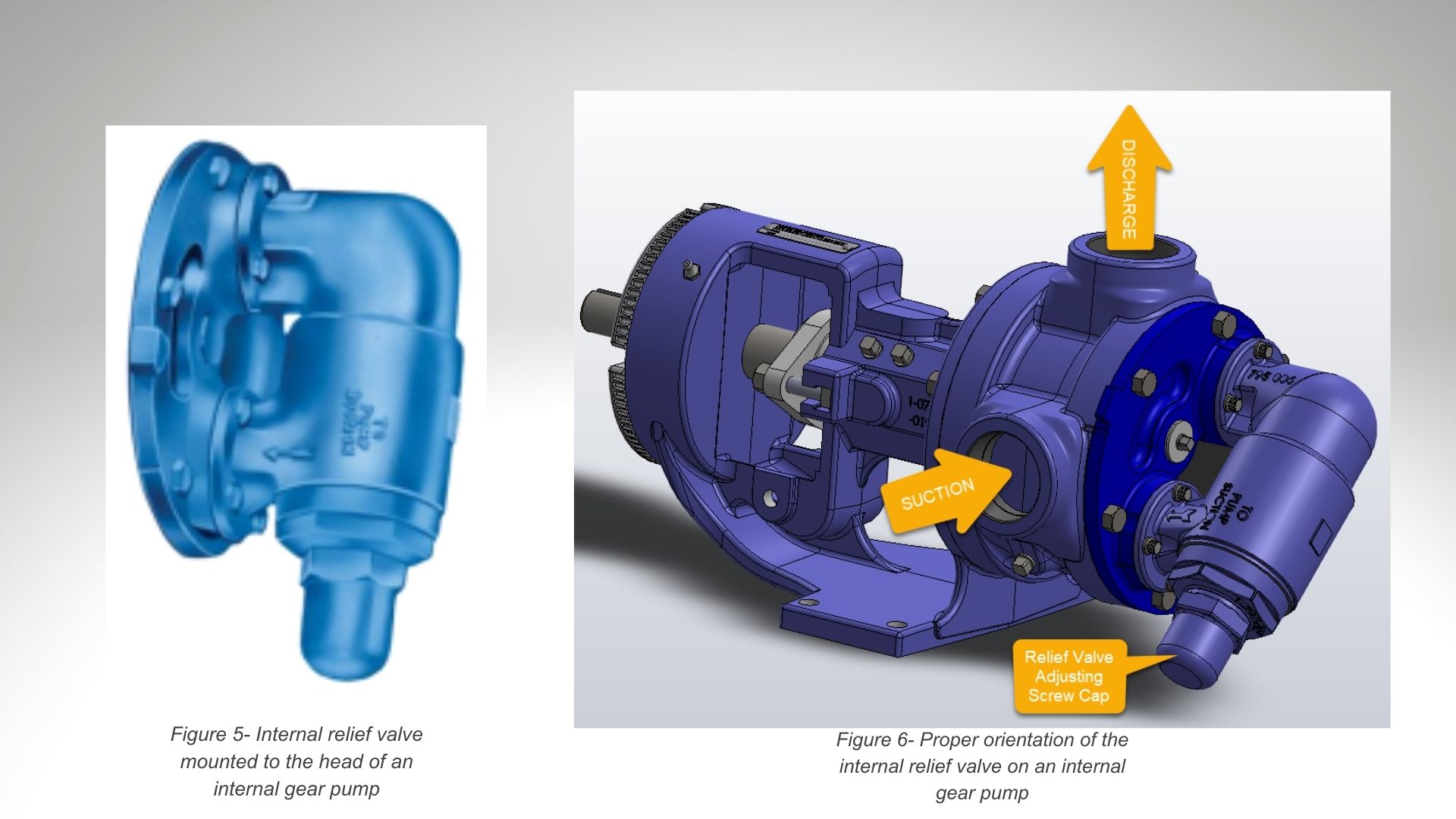
Internal relief valves are compact and require no additional steps to install, but it can be difficult to identify when they are in bypass and can result in heating of the liquid if run in full bypass at higher pressures or for long durations.
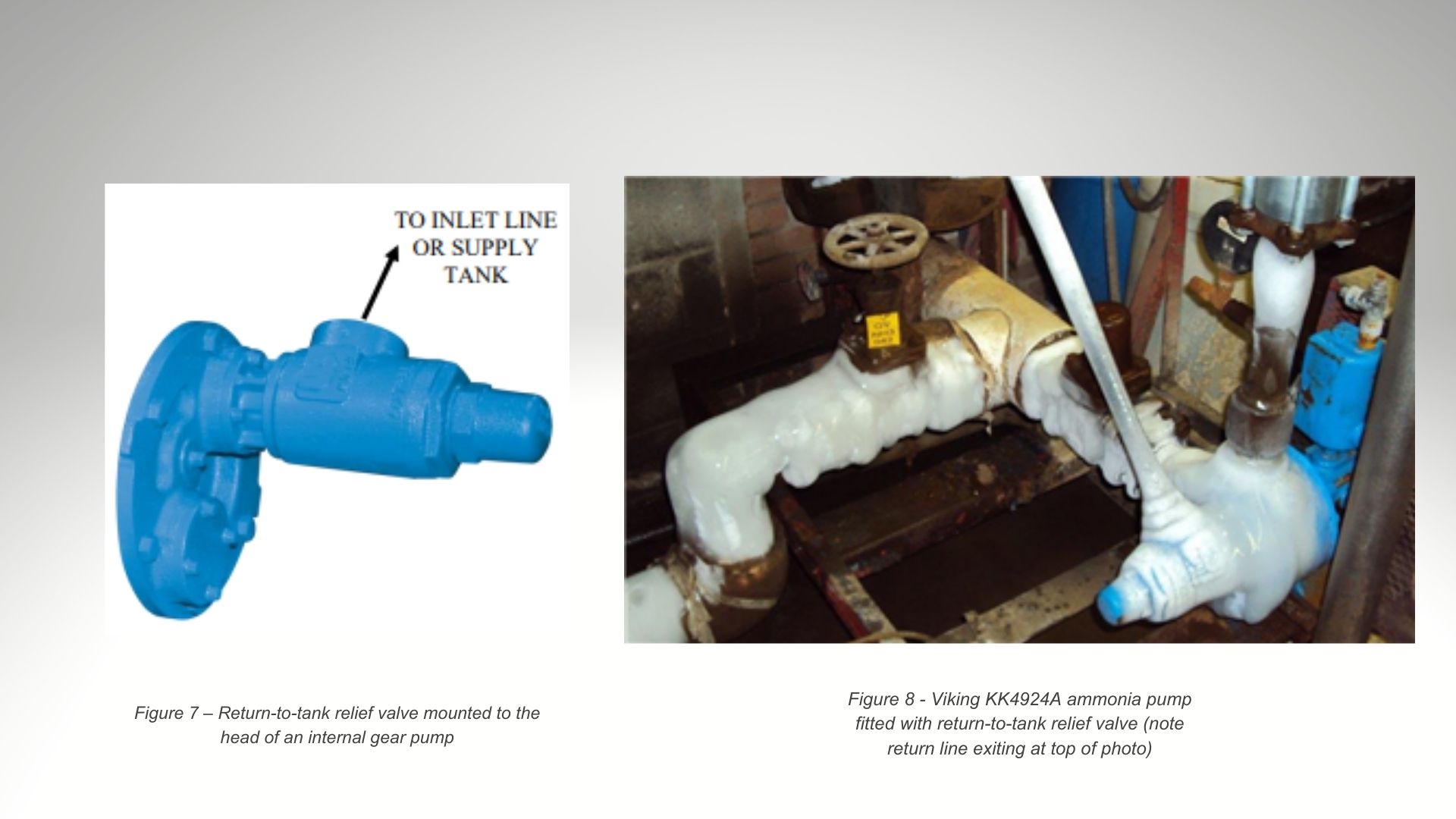
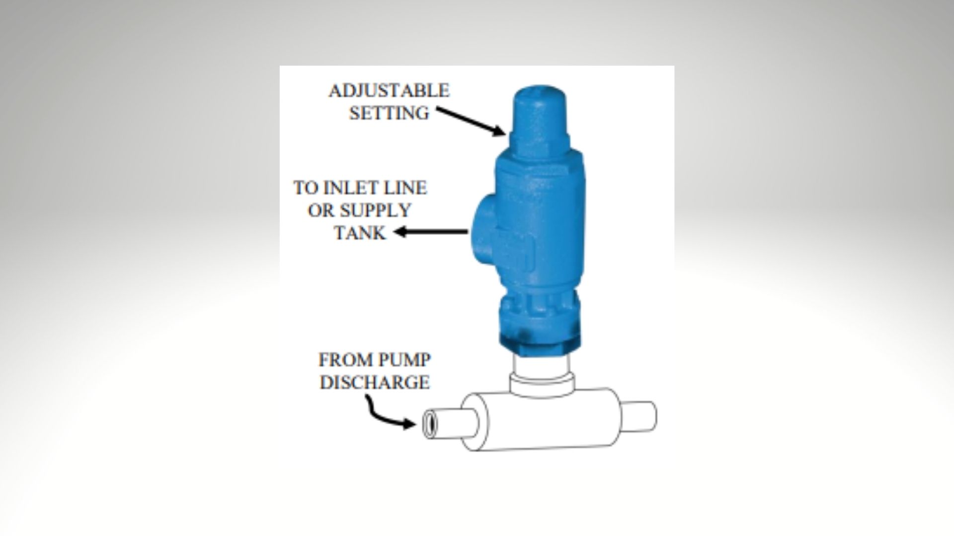
An alternative to the internal relief valve is the Return-To-Tank Relief Valve (see fig. 7). These valves operate just like the internal relief valve, but bypassed flow is directed back to the supply tank or a point on the inlet piping via pipes or hoses. While they do require additional piping, they can be piped in a way to observe whether they are in bypass and they carry heat way from the pump. For this reason, they are standard on Viking Pump’s 4924A Series™ Ammonia Pumps (see fig. 8).
Lastly are Inline Relief Valves (or System Relief Valves) (see fig. 9). These valves would be installed in the downstream piping and like the return-to-tank relief valve, require piping to direct bypassed flow to the supply tank or to a point on the inlet piping. These valves are favored when frequent bypass is required and are often used in conjunction with one of the other valve options. It’s important to remember not to include any isolation valves between the pump and a system relief valve as this introduces opportunity to overpressure the pump. If this is necessary, then a second relief valve on the pump will still be required.
As strange as it may sound, in an ideal system overpressure should never occur and the valve is never called into action. Pressure relief valves are not “flow control valves” nor are they “pressure regulators.” They are there only to prevent system overpressure should an upset condition occur.
And just like the TPR valve on a water heater, it’s best practice to have multiple means of overpressure protection. These may include, but not be limited to rupture discs, pressure transmitters, torque limiting devices, and motor protection devices.
Many Viking pumps have run for decades without the valve or other overpressure protection ever being called into service. But their inclusion in the pump system is essential to preventing serious, or even dangerous, failures should an upset condition occur. While often overlooked, the pressure relief valve is the ever-vigilant hero your pump system needs.