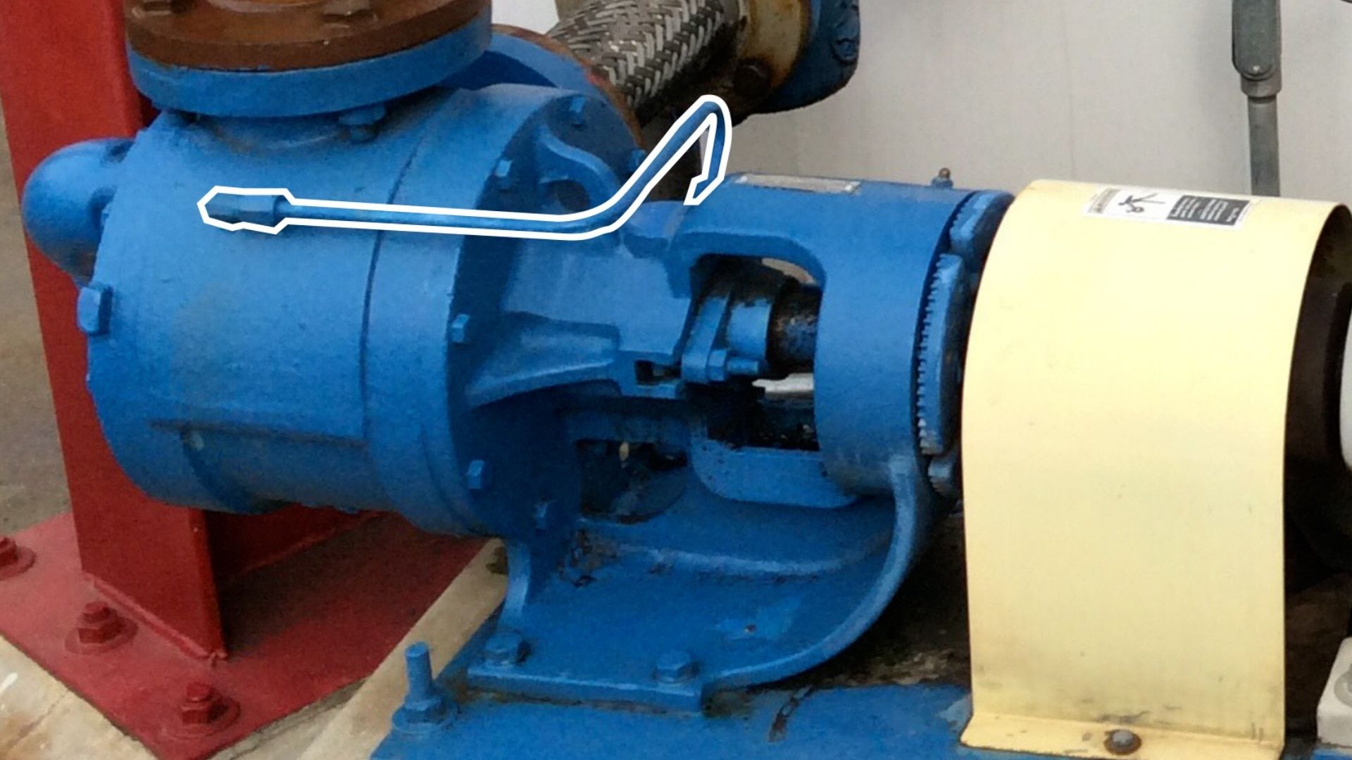
One of the biggest limitations of a traditional centrifugal pump is its inability to reverse the direction of flow. By design it can only be run in one rotation and one direction of flow. Liquid enters the eye of the impeller at the suction port (typically on the front of the pump), is pushed out radially, and exits the pump at the discharge port (typically on top of the pump). For most centrifugal pumps the suction port is larger than the discharge port to better feed liquid into the pump, and to remove any confusion as to which port is “in” and which port is “out.” Rotation arrows can be found cast onto the pump or printed on the nameplate to make it perfectly clear that these pumps run in one direction of rotation and one direction of flow.
So, what could happen if we run a centrifugal pump in reverse rotation? It varies by type and design, but there are several potential consequences:
- Reduced flow and head…oddly enough, flow is still going in the same direction, it’s just reduced (more on this shortly)
- Noise
- Seal failure
- Bearing failure
- The impeller, if threaded, can get loose from the shaft and damage the pump
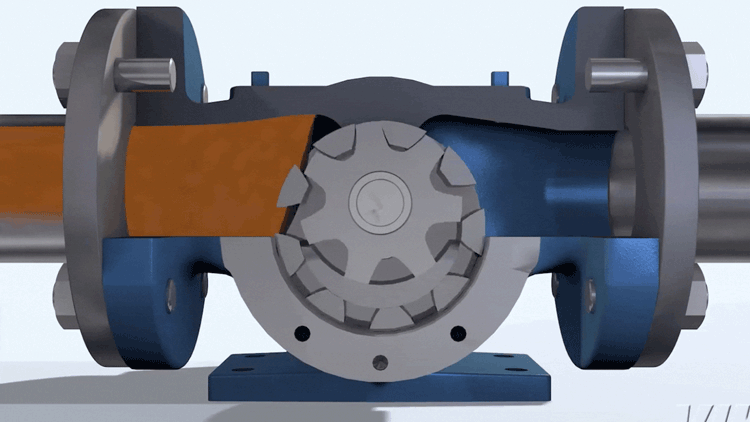
Which brings us to the subject at hand: running internal gear pumps in reverse. They can be easily converted from one direction of rotation and flow to the other; or even be made to run in two directions of rotation and in two directions of flow. The capacity of the pump remains constant in either direction, making this a beneficial and unique feature of the Internal Gear pumping principle.
The most common reason for changing a pump’s rotation is to accommodate the system. If the supply tank is on the right, then it’s not ideal to have the inlet port on the left. “Creative” piping can be used to accommodate the pump, but changing the pump’s rotation to swap the inlet and outlet ports makes for a cleaner system design, and avoids adding extra length and restrictions to the inlet piping. The pump can be ordered and built in either rotation, but sometimes the pump comes from your inventory or from another part of your facility. Rotation changes can happen for a variety of reasons.
Another common example is a pump which is going to be run in both rotations and both directions of flow. This is common for customers loading or unloading liquids through hoses or manifolds. Once the load is complete, they briefly run the pump in reverse to strip-clean the pipes. In these cases, there’s a primary direction of rotation and flow in which the pump runs most often, and a secondary direction of rotation and flow which is less frequent and usually shorter duration.
Least common are pumps that are run equally in both directions. This is critical to note, particularly to protect against upset conditions.
It’s important to know which scenario best fits for your pump:
- One Direction of Rotation and Flow
- Two Directions of Rotation and Flow (one which direction is the primary direction)
- Two Directions of Rotation and Flow (approximately equal time for both)
- Rotation Change Checklist
There are 4 key points to check before changing the rotation of an Internal Gear Pump:
- CAN THE PUMP BE REVERSED?
Most can, but there are a few exceptions that would need to be confirmed.
- DOES THE PUMP HAVE A RELIEF VALVE?
If so, it may need to be reoriented.
- DOES THE PUMP HAVE A SEAL CIRCULATION PLAN?
If so, it may need to be reversed or otherwise modified.
- DOES THE PUMP HAVE ANY INTERNAL LUBRICATION PATHS?
If so, they may need to be modified, if possible.
There are some outliers…designs of internal gear pumps that cannot be reversed. Before we get too far down this path it’s best to check first to make sure your pump does not show any “red flags” that would indicate that they fall into this group of “directional” pumps.
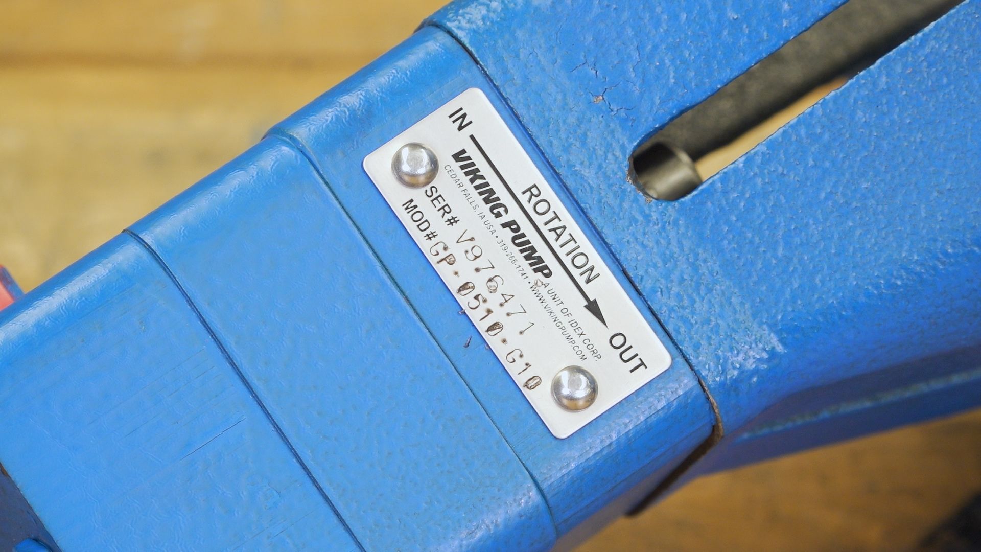
The first “red flag” would be a rotation arrow on the casting or nameplate of the pump. Common examples for Viking Pump include Mag Drive pumps from the 895 Series™ (rotation arrow on the nameplate), or the 4 inch and larger Motor Speed pumps from the 4195 Series™ (rotation arrow cast into the head). In either case, these pumps have design features that make them rotational, so running them in reverse rotation is not advised.
The second “red flag” would be differences in port sizes. Internal Gear pumps typically feature identical port sizes so that the inlet and outlet can be swapped. However, some pumps are designed to have a designated inlet and outlet port. In these cases, the inlet is always larger than the outlet for the same reason that this is done in centrifugal pumps (to better feed liquid into the pump and to remove any confusion as to which port is “in” and which port is “out”.)
If neither of these are applicable to your Internal Gear pump, then it’s likely that you can move on to question 2.
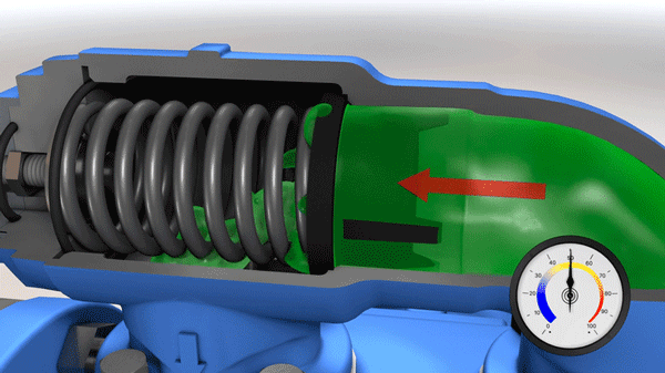
Viking pump-mounted relief valves, whether internal or return-to-tank, are directional. They only provide over-pressure protection in one direction of rotation and flow. Most are reversible though. By removing the valve from the pump, swapping the orientation by 180°, and reinstalling it, the direction of overpressure protection for the pump reversed. Modifying the valve orientation is the most common required modification for changing the direction of flow of an Internal Gear pump.
There are two important things to note:
First, there are a few Viking models where the relief valve is not a separate component, but rather built into the body of the pump itself. One common example of this is the smallest 432 Series™ sizes where the valve is built into the casing. For these models the direction of overpressure protection cannot be reversed.
Second, if a pump is to be run in both directions this could mean that an overpressure, upset condition could occur on either side of the pump. If running the pump in both directions, both sides of the pump need over-pressure protection. A Viking internal relief valve, which only functions in one direction of flow, could not be used as the only means of over-pressure protection.
Many pumps feature either an internal or external seal circulation plan. These include internal holes or external tubing which route pumped fluid through the seal chamber to help lubricate, and ultimately extend the life of, the seal and pump parts. Common examples include an API Plan 11 (or flush line), or an API Plan 13 (or suckback line). For these seal circulation plans a line is connected between the seal (or stuffing box) to the discharge port or suction port, respectively.
Reversing the rotation of the pump and direction of flow will reverse the flow through the seal plan, turning a Plan 11 into a Plan 13 (or vice versa). For some applications either API plan may be acceptable and no modifications would be needed. For others the appropriate seal circulation plan should be used; the line would need to be removed and replaced accordingly.
In a few models, the seal circulation plan is internal to the pump, and may or may not be easily changed. A common example of this is the 75 Series™, where a hole in the suction port ensures fresh liquid and low pressure at the seal. For these pumps the discharge side hole is plugged. When changing the direction of rotation, it would be necessary to move this plug to the other side of the casing.
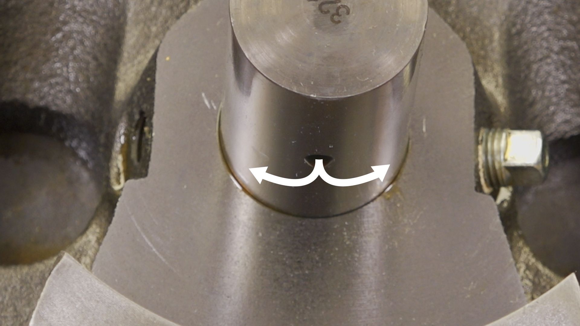
Some Internal Gear Pump models and sizes feature additional paths for internal lubrication of bushings, or to improve flow behind the rotor. A common feature is the pressure lubricated idler pin, which has a hole that allows liquid to be fed in from the discharge side of the pump and exit underneath the bushing. This helps to ensure the bushing and pin always have plenty of lubrication, and the life of these parts is extended. When reversing the rotation of the pump, this internal lubrication path reverses. While still providing lubrication, its effectiveness is somewhat diminished. It’s preferable to have the discharge side hole open to pressure-feed the idler pin. Often this can be done by sampling changing the location of a pipe plug (though some models and sizes feature check valves which require no modification to change direction).
Another, though somewhat less common, internal lubrication option is a casing groove. These are used to promote flow behind the rotor for liquids that may set up or settle out in the back of the casing. Casings with two grooves can be run in either direction. Casings with one groove are directional, and should be replaced before changing the primary pump rotation. In some cases a pump may be suitable running with either a flush groove (discharge side) or suckback groove (inlet side), but this should always be checked with your authorized Viking Pump distributor before making this change.
Fitted properly, most Viking Internal Gear Pumps can be run in either direction or both! After checking the list from above and making the proposed changes you will be ready to roll in a new direction.