Unlike most of my colleagues I didn’t start out with a mechanical background. While they were studying kinetics and machine design, I was studying digital electronics and industrial power. When I started my career in the world of pumps, I had to learn a whole new set of concepts. What was surprising was that while the terminology may be a bit different, the concepts are very similar. Think of the following as a “Rosetta Stone” for translating the common terms and concepts of fluid systems to your more familiar terms and concepts of electrical systems.
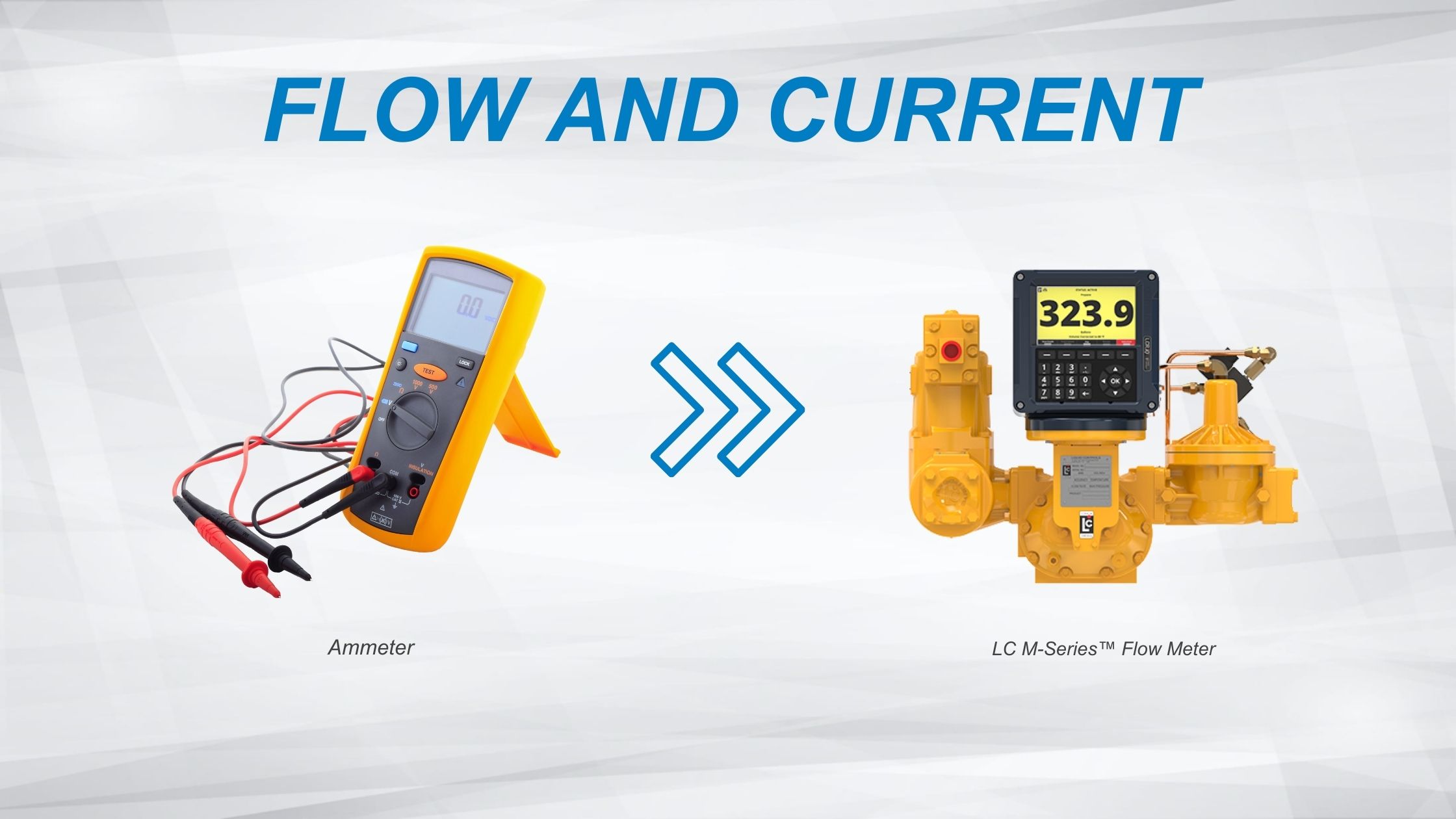
Electric current is the rate of flow of electric charge. Think of this as the rate of the flow of electrons passing through a conductor like wire. Current is most commonly represented by the symbol I and is most commonly measured in amperes (symbol A).
Flow (or more accurately, flow rate) is measurement of the volume of liquid travelling through a pumping system over a period of time. Flow rate is commonly represented by the symbol Q and is most commonly measured in gallons per minute (GPM) or cubic meters per hour (m³/hr). Another common variation of this is mass flow rate wherein the rate of flow is measured by the weight of liquid transferred over a period of time. This is commonly used by engineers who measure the weight of the vessels to determine the quantity of liquid transferred. For mass flow rate the common units of measure are pounds per minute (lb/min), kilograms per hour (kg/hr), or variations thereof.
Just as an ammeter would be placed in line to measure current, a flow meter would need to be placed in line to measure liquid flow rate.
Voltage, also called potential difference, is a difference in electric potential between two points. A battery is an excellent example of this, having a voltage across it that when connected in an electrical circuit causes a resulting current. Voltage is most commonly represented by the symbol V and is most commonly measured in volts (symbol V).
Pressure is a very similar concept. Just as current cannot exist without voltage, so too flow rate cannot exist without a pressure differential. In pumping systems the primary source of this pressure differential is the pump. Pressure is commonly represented by the symbol P and is most commonly measured in pounds of force per square inch (PSI), kilopascals (kPa), or bar.
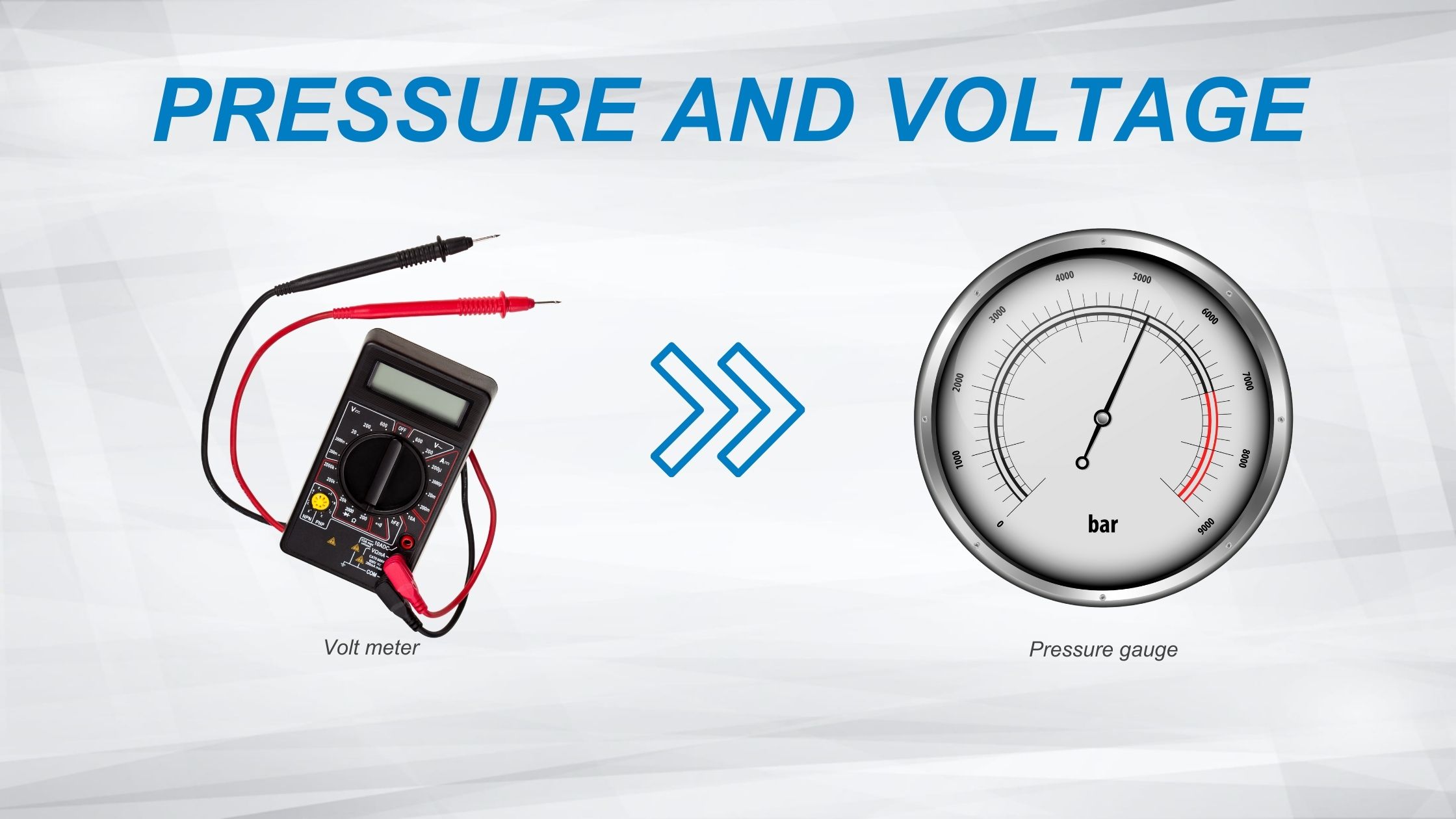
Voltage is measured using a voltmeter to compare the potential difference at two points of an electrical circuit. Pressure is measured using gauges which are also measuring a difference, but this is the pressure difference between the liquid in the pumping system and atmospheric pressure.
Resistance to electric current flow and resistance to liquid flow are identical concepts. In electrical systems resistance is represented by the symbol R and is most commonly measured in ohms (symbol Ω). Resistance naturally occurs in electrical systems…even the wires themselves, while highly conductive, do have some resistance. If resistance is desired to limit the current flowing through a portion of an electrical system, then resistors or potentiometers (variable resistors) can be utilized.
Resistance in fluid systems is based on more variables, specifically the viscosity of the liquid being pumped (i.e. there would be less resistance to water flow through a fluid system than there would be for heavy oil in the same system). Resistance to flow in fluid systems can come from filters, valves, and even the pipes themselves. Measuring resistance in fluid systems is normally done with differential pressure measurement. For example, if we suspect a filter of being clogged and causing high flow resistance, a high differential pressure measurement observed across the filter would confirm this.
Just as current follows the path of least resistance in an electrical circuit, so too does fluid flow follow the path of least resistance. Consider a fluid system that splits into two equal branches. Just like an electrical circuit, the flow rate in each branch would be equal and half of the total supplied flow rate. But if the losses in one of those two paths are doubled (i.e. the length of one leg of the fluid system is doubled) then two thirds of the flow follows the lower resistance leg with the remaining third passing through the higher resistance leg. Sound familiar? Yes, Ohm’s Law can be applied to fluid flow too.
Here’s where we need to be a little careful with the analogies. As I’d mentioned before, a battery is a source of voltage. Connecting that battery to a closed electrical circuit results in flow.
In that way, pumps are similar, but there are two main classifications of pumps and the way they generate flow in a fluid system is very different.
Centrifugal pumps which are most commonly used for water applications are pressure generating machines. The flow rate produced is a function of downstream resistance. Increasing resistance will result in decreasing flow rate. In this way they are very similar to batteries wherein voltage is produced, and the flow rate varies inversely with inline resistance.
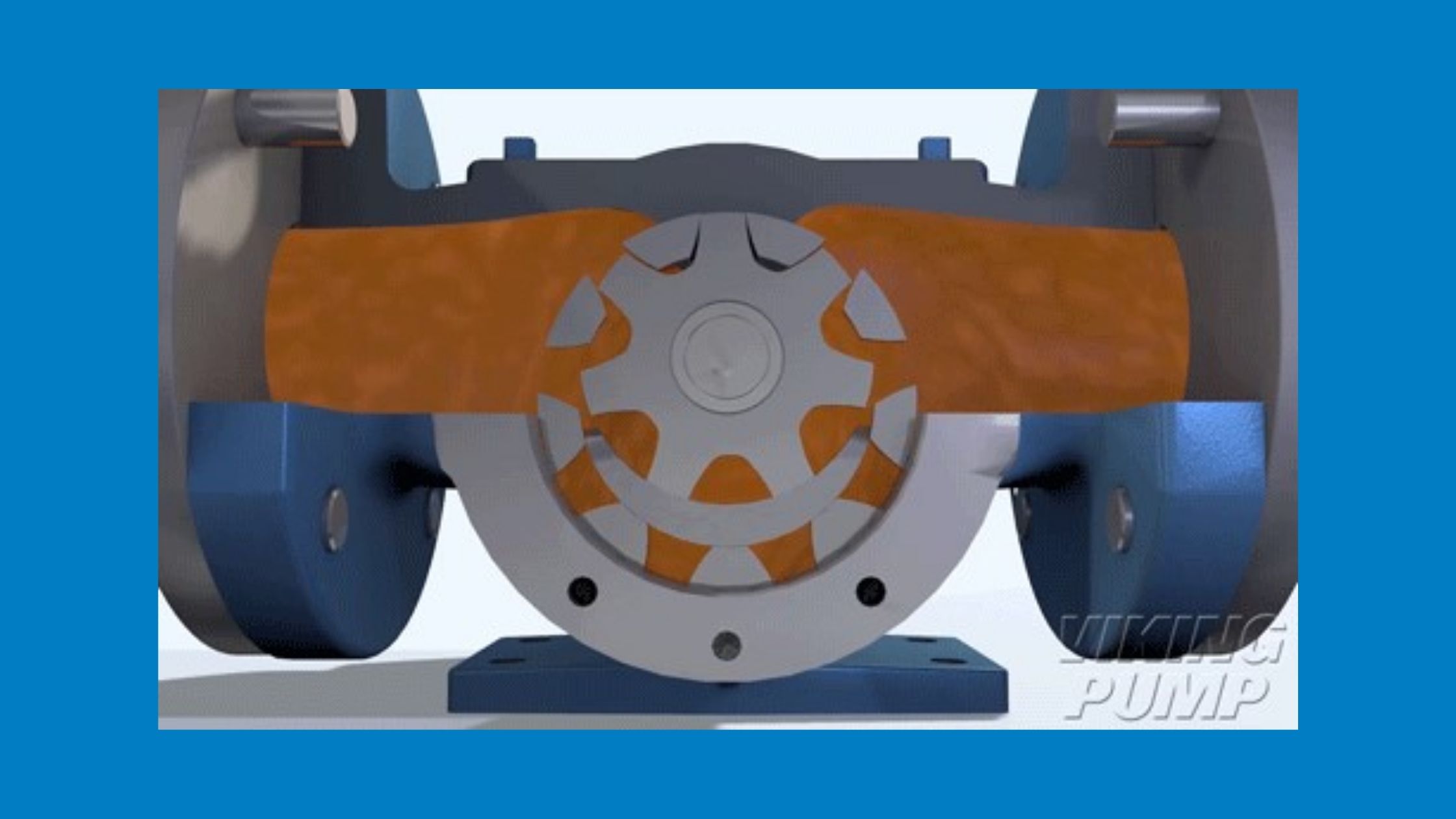
Positive displacement pumps like gear pumps or piston pumps operate differently. These are flow generating machines. The resulting pressure is a function of downstream resistance. Positive displacement pumps are more like a constant current power supply than a battery…with current remaining the same the voltage would change in response to changes in resistance.
The similarities don’t stop there:
- Diodes and Check Valves
- Current Limiting Devices and Pressure Limiting Devices
- Switches and Directional Control Valves
Just as understanding the relationship between voltage, current, and resistance is the key foundation to understanding electrical circuits, it’s critical to understanding the relationship between pressure, flow rate, and resistance to establish a foundation to understanding pumping systems. Understanding these basics leads to a better understanding of both electrical and fluid systems.